
Water level interlocking control system in air-cooled photo-thermal unit and interlocking control method thereof

A chain control and unit technology, applied in household refrigeration equipment, lighting and heating equipment, cooling fluid circulation equipment, etc., can solve problems such as radiator cracking, waste of water resources, increase equipment maintenance cycle and cost, and prevent Effects of freezing, improving safety, and reducing hidden dangers of system freezing

Pending Publication Date: 2019-09-03
NORTHWEST ELECTRIC POWER DESIGN INST OF CHINA POWER ENG CONSULTING GROUP
View PDF0 Cites 0 Cited by
  • Summary
  • Abstract
  • Description
  • Claims
  • Application Information

AI Technical Summary

Problems solved by technology

However, the auxiliary system of the conventional thermal power unit only relies on the method of electric heat tracing, which has the following problems. When the auxiliary system is started in severe cold winter conditions, when the cooling medium is filled into each cooling sector, due to the limited water flow velocity, the end of the water flow The radiator finned tubes are at risk of being frozen and blocking the pipes
At the same time, the frequent start and stop of the solar thermal unit will bring about the need for frequent filling and discharging of water in the water storage tank. If the water level is controlled to be higher than the maximum level, it will cause the water tank to overflow and drain, wasting water resources; The water in each sector cannot enter the water storage tank, that is, the radiator is also at risk of being frozen and cracked, which increases the maintenance cycle and cost of the equipment

Method used


Image

  • Water level interlocking control system in air-cooled photo-thermal unit and interlocking control method thereof

Examples


Embodiment Construction

[0027] In order to enable those skilled in the art to better understand the solutions of the present invention, the following will clearly and completely describe the technical solutions in the embodiments of the present invention in conjunction with the drawings in the embodiments of the present invention. Obviously, the described embodiments are only It is an embodiment of a part of the present invention, but not all embodiments. Based on the embodiments of the present invention, all other embodiments obtained by persons of ordinary skill in the art without making creative efforts shall fall within the protection scope of the present invention.

[0028] It should be noted that the terms "first" and "second" in the description and claims of the present invention and the above drawings are used to distinguish similar objects, but not necessarily used to describe a specific sequence or sequence. It is to be understood that the data so used are interchangeable under appropriate ...


PUM


Abstract

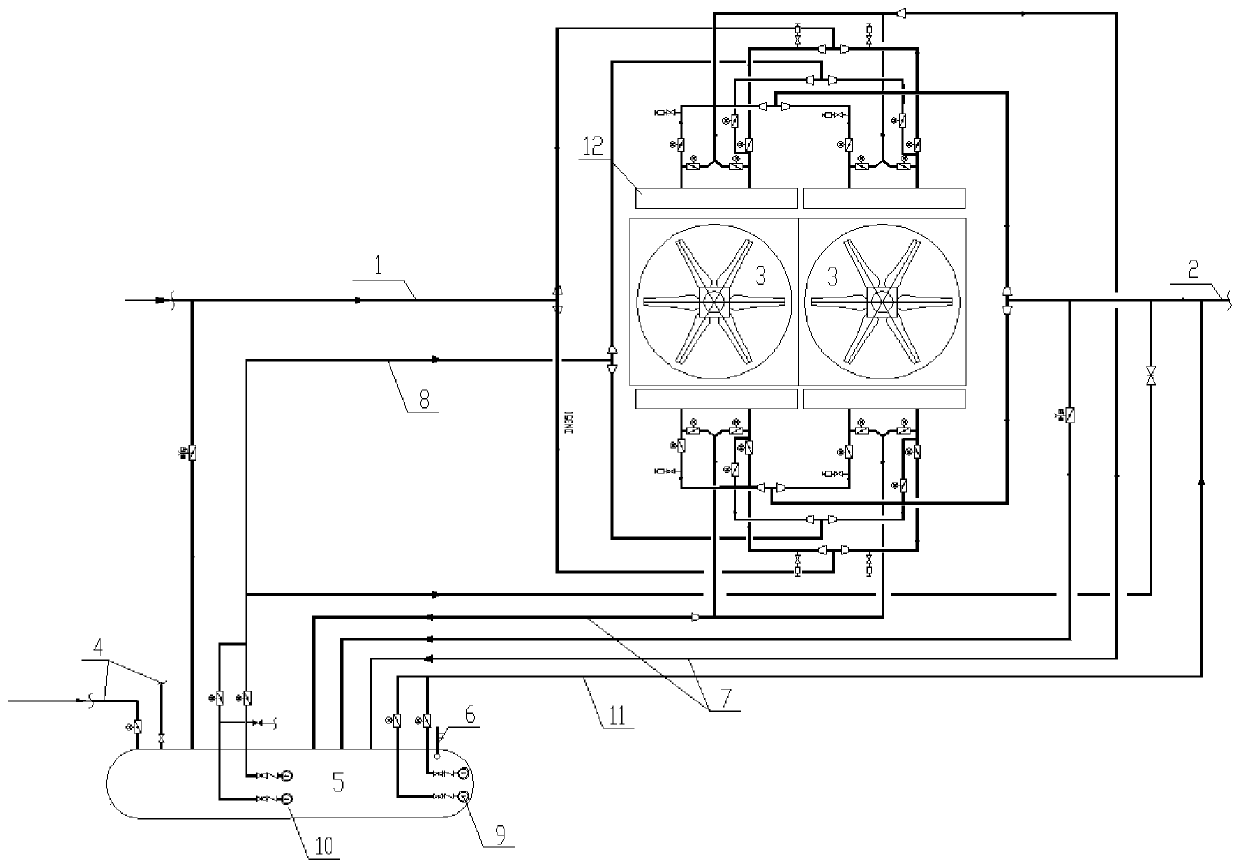
The invention discloses a water level interlocking control system in air-cooled photo-thermal unit and an interlocking control method of the water level interlocking control system in the air-cooled photo-thermal unit, and belongs to the field of solar energy development and utilization. According to the interlocking control method of the water level interlocking control system in the air-cooled photo-thermal unit, when the control system normally operates, circulating water in auxiliary machine equipment enters a branch where a cooling fan section is located through an auxiliary machine cooling water pipe, enters a corresponding cooling fan section through a valve on the branch and is cooled in the cooling fan section, and the cooled circulating water enters the auxiliary machine equipment again through an auxiliary machine return water pipe; and when the water temperature is lower than the preset temperature, cooling water in an auxiliary machine dry cooling tower flows back to a water storage tank from a first inlet through an outlet of the corresponding cooling fan section, and circulating water in the auxiliary machine cooling water pipe enters the water storage tank from a second inlet. According to the interlocking control method, the system anti-freezing hidden danger caused by frequent startup and shutdown of the photo-thermal unit is greatly reduced, and operation safety of equipment is improved.

Description

technical field [0001] The invention belongs to the field of solar energy development and utilization, in particular to a water level chain control system in an air-cooled photothermal unit and a chain control method thereof. Background technique [0002] Solar energy is a kind of clean renewable energy, which is inexhaustible and inexhaustible, so it has developed vigorously in recent years. my country's solar direct radiation resources and available land resources are concentrated in the northwestern region of our country, and the northwestern region is extremely cold in winter, so the antifreeze situation is particularly severe. However, the auxiliary system of conventional thermal power units only relies on electric heat tracing, which has the following problems. When starting the auxiliary system in severe cold winter conditions, when the cooling medium is filled into each cooling sector, due to the limited water flow velocity, the end of the water flow The finned tube...

Claims


Application Information

Patent Timeline
Patent Type & Authority Applications(China)
IPC IPC(8): F25D29/00F25D17/02
CPCF25D29/001F25D17/02F25D2600/06Y02E10/40
Inventor 高霞娥高志广付文刚张爱军李诚
Owner NORTHWEST ELECTRIC POWER DESIGN INST OF CHINA POWER ENG CONSULTING GROUP
Learn More