Novel micro nano fiber Bragg grating refractive index sensor

A technology of refractive index sensor and Bragg grating, which is applied in the direction of converting sensor output, using optical devices to transmit sensing components, instruments, etc., can solve problems such as multiple effective signal bandwidths, signal annihilation, and expansion of the initial wavelength difference of reflected signals. Achieve the effect of avoiding occupation and crosstalk between signals, avoiding "water absorption" area, and high degree of commercialization

Active Publication Date: 2019-09-03
JINAN UNIVERSITY
View PDF4 Cites 5 Cited by
  • Summary
  • Abstract
  • Description
  • Claims
  • Application Information

AI Technical Summary

Problems solved by technology

However, this method has the following problems: 1) the use of rectangular cladding fiber will inevitably lead to the increase of cost and the compatibility of the transmission system; The ability to distinguish parameters, and increasing the birefringence will further expand the initial wavelength difference of the reflected signals in two orthogonal polarization directions, thus occupying more effective signal bandwidth, which is not conducive to future multi-parameter measurements based on wavelength division multiplexing systems development needs
Since the refinement of the optical fiber will cause a large blue shift of the Bragg resonance wavelength, the high-order mode coupling signal at the traditional design wavelength will appear in the "water absorption" region of the optical fiber, causing problems such as a decrease in the signal-to-noise ratio or even annihilation of the signal.

Method used


Image

  • Novel micro nano fiber Bragg grating refractive index sensor
  • Novel micro nano fiber Bragg grating refractive index sensor
  • Novel micro nano fiber Bragg grating refractive index sensor

Examples


Embodiment

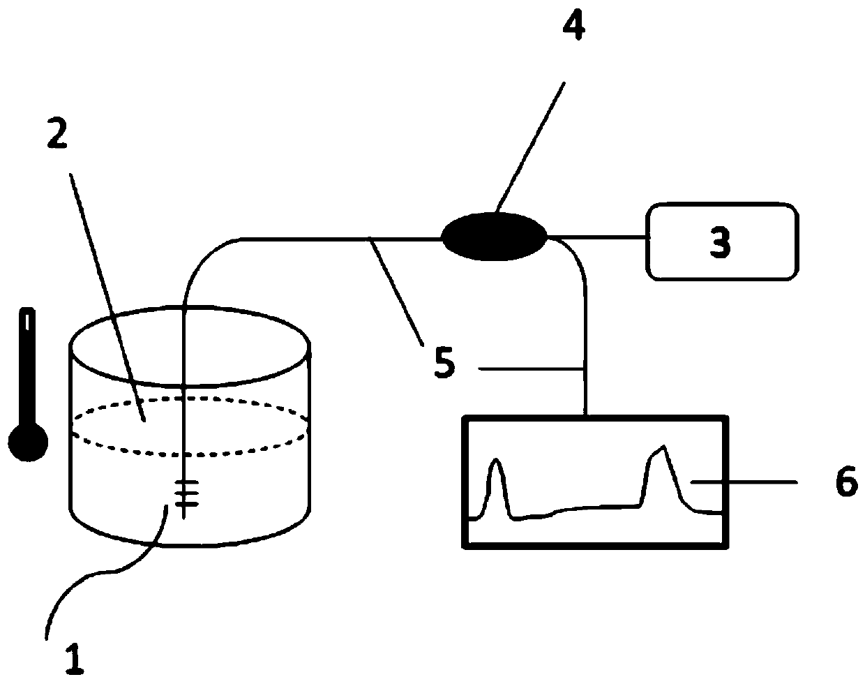
[0037] A new type of micro-nano fiber Bragg grating refractive index sensor, such as figure 1 As shown, it includes a broadband light source 3, an optical coupling element 4, a micro-nano fiber Bragg grating 1 connected in sequence, and a wavelength detection unit 6 connected to the optical coupling element 4; between the broadband light source 3 and the optical coupling element 4, the optical fiber The coupler 4 is connected with the micro-nano fiber Bragg grating 1 , the optical coupling element 4 and the wavelength detection unit 6 through a single-mode communication optical fiber 5 .

[0038] After the broadband optical signal emitted by the broadband light source 3 passes through the optical coupling element 4, it is incident on the micro-nano fiber Bragg grating 1 in the solution 2 to be tested, and the micro-nano fiber Bragg grating 1 is inserted into the solution 2 to be tested as a sensing probe Among them, the spectral lines of the micro-nano fiber Bragg grating 1 ar...


PUM

PropertyMeasurementUnit
diameteraaaaaaaaaa
diameteraaaaaaaaaa
diameteraaaaaaaaaa

Abstract

The invention discloses a novel micro nano fiber Bragg grating refractive index sensor, which comprises a broadband light source, an optical coupling element and a micro nano fiber Bragg grating connected in sequence, and a wavelength detecting unit connected to the optical coupling element, wherein optical signals emitted by the broadband light source are incident on the micro nano fiber Bragg grating through the optical coupling element, is reflected by the micro nano fiber Bragg grating and is then incident to the optical wavelength detecting unit through the optical coupling element; and the micro nano fiber Bragg grating has multiple higher harmonic reflection signals, the difference in sensitivity of the wavelength of each harmonic reflection signal to the ambient refractive index isdifferent from the sensitivity to the ambient temperature, and the ambient refractive index and the temperature can be measured at the same time. The novel micro nano fiber Bragg grating refractive index sensor has the advantages that the structure is compact, the cost is low, the making efficiency is high, effective bandwidth occupation is reduced, and the realization method is simple.

Description

technical field [0001] The invention relates to the research field of optical fiber grating refraction sensors, in particular to a novel micro-nano optical fiber Bragg grating refractive index sensor. Background technique [0002] With the advantages of low cost, flexible structure, biocompatibility, electrical insulation, and remote measurement, optical fiber biochemical sensors have developed rapidly in recent years. [0003] The optical fiber evanescent field biochemical sensor uses the evanescent wave generated by the light wave at the interface between the optical fiber and the external environment to feed back the specific biochemical reaction information on the surface of the optical fiber to the optical transmission signal through the change of the refractive index. Therefore, as long as the optical signal parameters Tracking enables label-free detection of biochemical quantities. This detection method is only related to the concentration of the analyte and does not...

Claims


Application Information

Patent Timeline
Patent Type & Authority Applications(China)
IPC IPC(8): G01D5/353G01N21/41G01K11/32G01K11/3206
CPCG01D5/35367G01N21/41G01K11/3206
Inventor 冉洋龙俊求徐志远关柏鸥
Owner JINAN UNIVERSITY
Why Eureka
Try Eureka