
Chip and packaging method thereof

A chip packaging and chip technology, which is applied in semiconductor/solid-state device components, semiconductor devices, electrical components, etc., can solve the problems of large overall size of the packaging structure and cannot meet the miniaturization of chips, and achieve the effect of reducing chip costs

Inactive Publication Date: 2019-09-03
HUAWEI TECH CO LTD
View PDF2 Cites 31 Cited by
  • Summary
  • Abstract
  • Description
  • Claims
  • Application Information

AI Technical Summary

Problems solved by technology

[0005] However, in the existing fan-out wafer-level packaging structure, the pins on the bare chip that are used to electrically connect to the periphery of the packaging structure need to pass through the substrate to realize the electrical connection with the periphery of the packaging structure. In this way, the overall size of the packaging structure Larger, cannot meet the needs of chip miniaturization

Method used


Image

  • Chip and packaging method thereof
  • Chip and packaging method thereof
  • Chip and packaging method thereof

Examples


Embodiment Construction

[0096] Before introducing the specific implementation of the embodiment of this application, first describe the definitions of abbreviations and key terms used in the embodiment of this application.

[0097]

[0098] Fan-out wafer-level packaging can lead out the I / O pins of a single chip through the rewiring layer on the wafer, increasing the area of ​​a single package, thereby increasing the overall number of I / O pins. Its design difficulty is not only lower than that of TSV 3DIC, but also the packaging structure is close to 2.5D IC. Therefore, fan-out wafer level packaging is expected to become the key point of the development of advanced packaging technology.

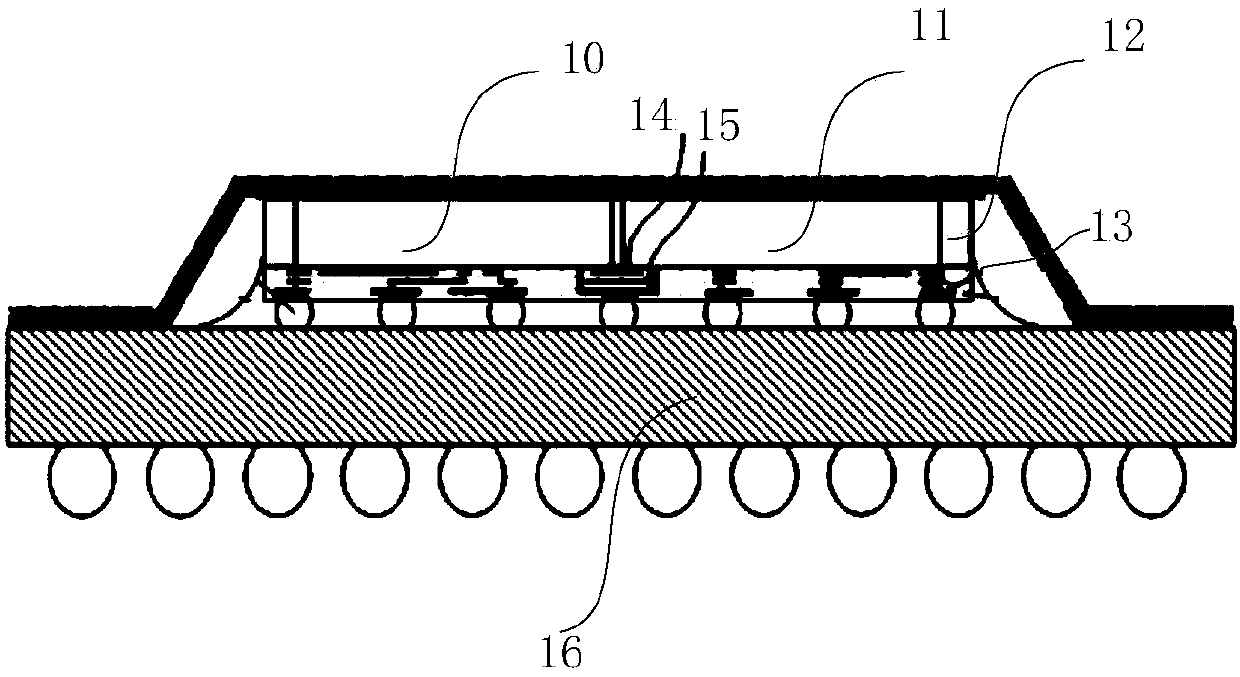
[0099] At present, some fan-out wafer-level packaging technologies have emerged in the industry. Among them, an existing fan-out packaging structure such as figure 1 shown. The fan-out packaging structure is a 2.5D FOP packaging structure combining traditional fan-out wafer level packaging and flip-chip packagi...


PUM


Abstract

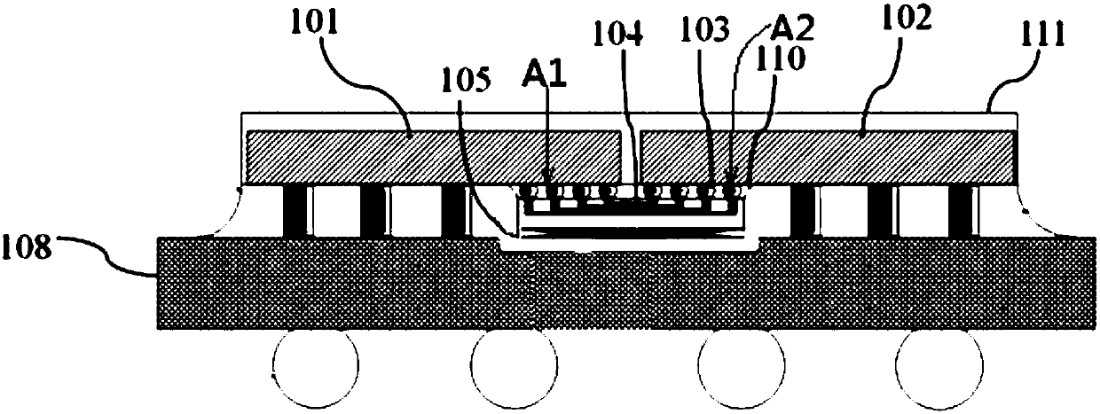
The embodiment of the application discloses a chip and a packaging method thereof. In the chip, the respective first bonding pads on a first bonding pad array on a first substrate are attached to respective corresponding second pins in second pin arrays on different bare chips, thereby achieving short-distance high-density interconnection between bare chips. A plastic package body is used for wrapping first pins, the second pins, the first bonding pads and the first substrate, so that a fan-out unit and the first substrate are plastically packaged into a unitary structure. In the unitary structure, the bottoms of the respective first pins of the first pin array on the bare chips to be electrically connected to the peripheries of the chips are not wrapped in the plastic package body, such that the respective first pins can be directly electrically connected to the peripheries of the chips. The overall size of the chip provided by the embodiment of the application is mainly determined bythe size of the plurality of integrated bare chips. Compared with the prior art, the chip provided by the embodiment of the application is small in overall size, and can meet a chip miniaturization requirement.

Description

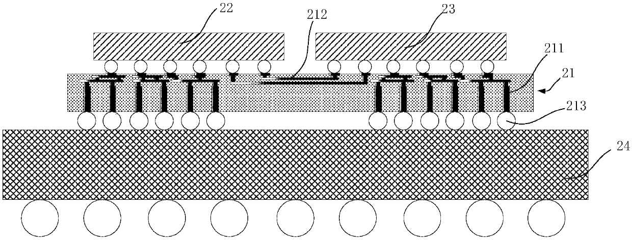
technical field [0001] This field relates to the technical field of semiconductor packaging, in particular to a chip and a packaging method. Background technique [0002] With the continuous development of integrated electronic technology, the requirements for chip performance are also increasing, such as function enhancement, size reduction, energy consumption and cost reduction, etc., thus giving birth to 3DIC (Three Dimensional Integrated Circuit, three-dimensional integrated circuit) technology. Silicon Interposer (Silicon Interposer) technology is a technical solution to realize the interconnection of stacked chips in three-dimensional integrated circuits. This technical solution uses semiconductor technology to manufacture interconnection lines on silicon wafers with much smaller line width and node spacing than resin substrates. In this way, chips with different functions such as CPU and DRAM can be connected to the same silicon interposer, and a large number of calc...

Claims


Application Information

Patent Timeline
IPC IPC(8): H01L21/56H01L23/498H01L27/02
CPCH01L21/56H01L23/492H01L21/60H01L23/293H01L23/31H01L2924/15311H01L2924/15192H01L2224/96H01L2924/18161H01L2224/1403H01L24/17H01L25/0655H01L2224/16227H01L24/96H01L2224/13082H01L24/14H01L24/16H01L24/81H01L23/5383H01L23/5384H01L23/5385H01L23/49816H01L23/13H01L23/49827H01L21/563H01L23/3128H01L2224/131H01L2224/13147H01L2224/73209H01L2224/12105H01L2224/04105H01L2924/18162H01L2924/351H01L2224/73267H01L2924/3511H01L2224/32245H01L2224/73204H01L2224/32225H01L2224/92125H01L2924/19105H01L2924/15788H01L2924/157H01L2924/1579H01L2224/0401H01L2224/16145H01L2224/0557H01L2224/14181H01L2224/32145H01L25/0652H01L2924/1431H01L2225/06541H01L2225/06513H01L2225/06527H01L2224/11H01L2224/81H01L2924/014H01L2924/00014H01L2924/00H01L2224/16225H01L21/4853H01L21/4857H01L23/3185H01L23/3675H01L23/5381H01L23/562H01L23/49811H01L25/50H01L23/5386
Inventor 赵南谢文旭陶军磊蒋尚轩符会利
Owner HUAWEI TECH CO LTD
Learn More