Electric connector with shielding and self-locking functions applied in 30kV high-voltage equipment system

A technology for electrical connectors and high-voltage equipment, which is applied in the direction of connection, installation of connection parts, and two-part connection device, etc. It can solve problems such as electromagnetic interference and poor contact, and achieve the effects of convenient maintenance and replacement, easy and fast operation, and good circuit contact

Pending Publication Date: 2019-09-03
RES INST OF PHYSICAL & CHEM ENG OF NUCLEAR IND +1
View PDF0 Cites 2 Cited by
  • Summary
  • Abstract
  • Description
  • Claims
  • Application Information

AI Technical Summary

Problems solved by technology

However, the insulation withstand voltage performance of current high-voltage electrical connectors is usually below 10,000V, which cannot meet the requirements of higher voltages.
At the same time, in harsh environments such as electromagnetic radiation pollution, existing high-voltage electrical connectors are prone to poor contact and electromagnetic interference.

Method used


Image

  • Electric connector with shielding and self-locking functions applied in 30kV high-voltage equipment system
  • Electric connector with shielding and self-locking functions applied in 30kV high-voltage equipment system
  • Electric connector with shielding and self-locking functions applied in 30kV high-voltage equipment system

Examples


Embodiment 1

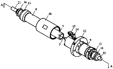
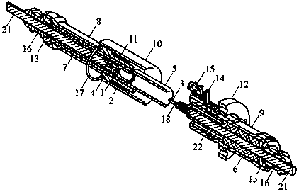
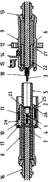
[0047] Such as Figure 1~3 As shown, an electrical connector with shielding and self-locking functions applied in a 30kV high-voltage equipment system includes a conductor assembly, an insulation assembly, a lock assembly, and a shield assembly.

[0048] The conductor assembly includes a finger spring 1, a conductor socket 2, a conductor plug 3 and a pressure equalizing ring 4 at the tail of the socket;

[0049] The contact finger spring 1 is arranged inside the conductor socket 2; the tail end of the conductor socket 2 is crimped with the cable 21, and the outer wall of the small diameter end is threaded with the pressure equalizing ring 4 at the tail of the socket; the tail end of the conductor plug 3 is crimped with the cable 21 on the other side , which is arranged at the head end of the insulating sleeve 6 on the flange side, and an outer retaining spring 18 for limiting is arranged on the outside;

[0050] The conductor socket 2 is limited in the insulating sleeve 5 on ...

Embodiment 2

[0067] Such as Figure 1~3 As shown, the electrical connector further includes a microswitch 15 for providing a mating signal of the connector to the system, which is arranged outside the flange-side housing 9 through the bracket 14 .

Embodiment 3

[0069] Such as Figure 4 , 5 As shown, the electrical connector also includes a socket 19 and a protective cover 20 for protecting the conductor plug 3 when the equipment is overhauled or the connector is not mated. Assume.

[0070] Effect of the present invention:

[0071] 1. Conductor performance: The conductor components are made of copper alloy or oxygen-free copper, and the surface is treated with silver plating, which reduces the conductor resistance and prevents oxidation. The contact finger spring 1 makes the inner wall of the conductor socket 2 and the conductor plug 3 tightly combined, which effectively reduces the contact resistance and heat generation; the conductor plug 3 is coated with a small amount of grease to ensure less wear and tear within the designed plug-in service life and relatively stable contact resistance. The structure of the metal parts is simple and compact, and the outer diameter of the cables is basically the same, which makes the structure ...


PUM


Abstract

The invention provides an electric connector with shielding and self-locking functions applied in a 30kV high-voltage equipment system. The connector comprises a conductor component, an insulation component, a lock catch component and a shielding component. The shape and the structure of the electric connector are circular single-core direct-insertion locking type with a spring, a flange at a socket end can be vertically installed and connected with the outer surface of a device or a cavity, and a plug end is handheld or operated by an instrument to perform plug-in locking; with the maximum external dimension, and the electric connector can be held one hand, and can be plugged and pulled and rotated, and locked and unlocked by both hands; the electric connector has an electromagnetic interference shielding function, the working voltage and current of the electric connector are 30kVd.c., 30A; and the high-voltage insulation test of the electric connector is 50kV for 5mins. The electricconnector can achieve the good circuit contact in a severe environment such as an electromagnetic shielding pollution, is safe and reliable in insulation, continuous and stable in shielding, simple and compact in structure, easy and rapid in operation and convenient to repair and replace.

Description

technical field [0001] The invention belongs to a high-voltage electrical connector, in particular to an electrical connector with shielding and self-locking functions applied in a 30kV high-voltage equipment system. Background technique [0002] Most of the existing high-voltage circuit cable connections are fixed connections, and the installation site performs protective treatment on the connection points, which cannot form a standardized operation. Whether the protection level meets the requirements is judged by the operator, which will cause individual differences and lead to inconsistent standards. In order to solve the inadequacy of standardized operations, electrical connectors can be used for connection. High-voltage electrical connectors are key components connecting high-voltage circuits and high-voltage equipment, which will affect the architecture and design of the entire system. The electrical connectors are manufactured in the factory and uniformly inspected w...

Claims


Application Information

Patent Timeline
IPC IPC(8): H01R13/03H01R13/187H01R13/40H01R13/502H01R13/53H01R13/629H01R13/639H01R13/641H01R13/6581H01R13/6593H01R13/73H01R24/00
CPCH01R13/03H01R13/187H01R13/40H01R13/53H01R13/639H01R13/641H01R13/6593H01R13/6581H01R13/73H01R13/629H01R13/502H01R24/005
Inventor 贾子朝周小明成成高学林张帆王洪强
Owner RES INST OF PHYSICAL & CHEM ENG OF NUCLEAR IND
Why Eureka
Try Eureka