Sensor and method for detecting normal stress and shear force of sole precisely during walking

A normal stress and shear force technology, applied in the direction of sensor, application, diagnostic recording/measurement, etc., can solve the problem of inability to provide shear force data, and achieve the effect of simple structure, reducing measurement error and reducing crosstalk.

Pending Publication Date: 2019-09-06
北京中硕众联智能电子科技有限公司
View PDF1 Cites 2 Cited by
  • Summary
  • Abstract
  • Description
  • Claims
  • Application Information

AI Technical Summary

Problems solved by technology

The above techniques can only simply collect the distribution of plantar pressure, but cannot provide data on shear force

Method used


Image

  • Sensor and method for detecting normal stress and shear force of sole precisely during walking
  • Sensor and method for detecting normal stress and shear force of sole precisely during walking
  • Sensor and method for detecting normal stress and shear force of sole precisely during walking

Examples


Embodiment 1

[0059] Example 1 An insole that accurately detects plantar normal stress and shear force during walking

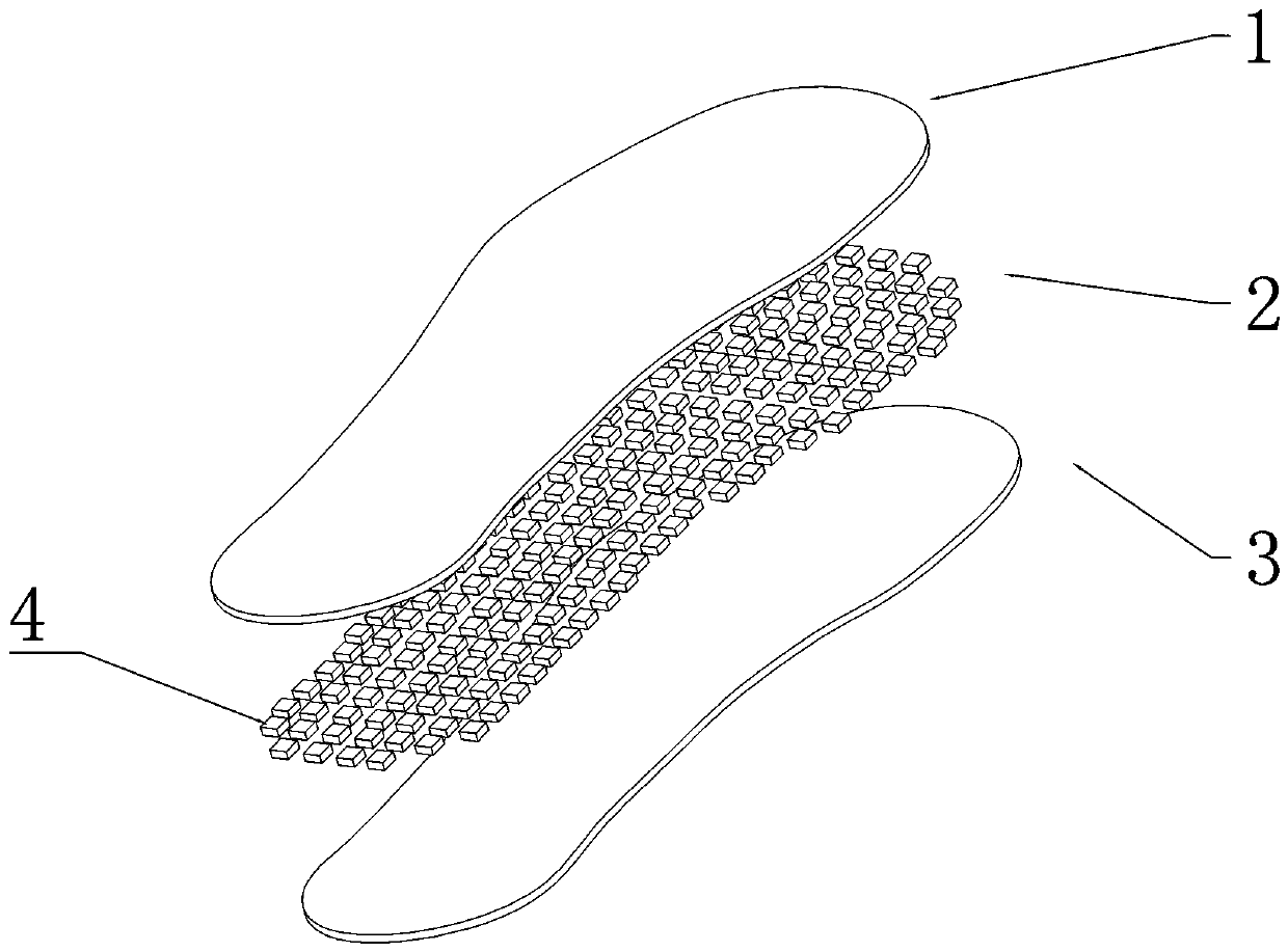
[0060] This embodiment relates to an insole for accurately detecting the normal stress and shear force of the sole during walking, including a signal acquisition part and a back-end circuit, and the signal output end of the signal acquisition part is connected to the signal input end of the back-end circuit. Such as figure 1 As shown, the signal acquisition part includes a first device protection layer 1, a signal acquisition array 2 and a second device protection layer 3 arranged in sequence from top to bottom; wherein, the signal acquisition array 2 includes several detection units 4 distributed according to the shape of the sole .

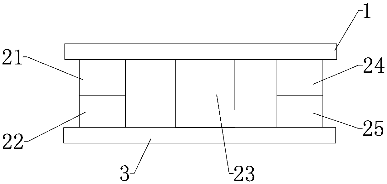
[0061] Such as figure 2 As shown, the detection unit 4 includes a first electrode 21, a third electrode 23, and a second electrode 24 arranged side by side and spaced apart. A first piezoelectric film 22 is arranged between the first elec...

Embodiment 2

[0065] Example 2 A method for accurately detecting plantar normal stress and shear force during walking

[0066] This embodiment adopts Embodiment 1 to realize, and carries out according to the following steps in sequence:

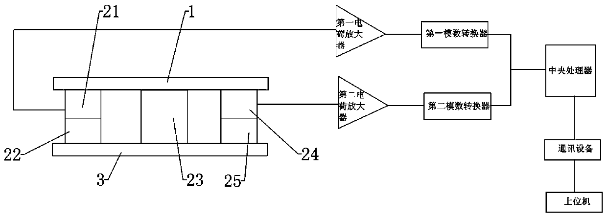
[0067] 1. Place the insole in the shoe, and the subject puts on the shoe and walks. When the normal stress on the detection unit 4 changes, the surface of the first piezoelectric film 22 generates charges; when the detection unit 4 moves along the second piezoelectric film 25 When the shear force in the direction changes, the surface of the second piezoelectric film 25 generates charges;

[0068] 2. This step includes the following steps carried out in sequence,

[0069] (1) The first charge amplifier collects the charge generated on the surface of the first piezoelectric film 22 and amplifies it into an analog voltage signal and outputs it to the first analog-to-digital converter, and the second charge amplifier collects the charge generated on the surfa...


PUM


Abstract

The invention discloses a sensor for detecting normal stress and shear force of a sole precisely during walking. The sensor comprises a signal acquisition portion and a backend circuit; the signal output end of the signal acquisition portion is connected with the signal input end of the backend circuit; the signal acquisition portion comprises a first device protective layer, a detection unit anda second device protective layer arranged sequentially from top to bottom; the detection unit comprises a first electrode, a third electrode and a second electrode arranged side by side at intervals;a first piezoelectric film is arranged between the first electrode and the second device protective layer; a second piezoelectric film is arranged between the second electrode and the second device protective layer. The invention also discloses a method for detecting normal stress and shear force of a sole precisely during walking. The sensor and method are suitable for measuring normal stress andshear force at the same time; defects of existing products are made up; richer, more comprehensive data are provided for the measurement of sole pressure; the method has simple steps, is easy to implement and is extensible in the field of sole pressure detection.

Description

technical field [0001] The invention belongs to the technical field of medical equipment and is used for accurately detecting the normal stress and shearing force of the sole during walking, in particular to a sensor and a detection method for accurately detecting the normal stress and shearing force of the sole during walking. Background technique [0002] With the improvement of living standards, human health has become an important issue of concern. According to the biological holographic theory, the foot is related to the internal organs and various organs of the human body, and has its corresponding reflection area. It can be seen that the foot has a close relationship with human health and longevity. [0003] The distribution of human plantar pressure can reflect the function of lower limbs and changes in body posture. By testing and analyzing the pressure parameters of each point on the sole of the foot, the physiological and pathological parameters of the human body...

Claims


Application Information

Patent Timeline
IPC IPC(8): A61B5/103
CPCA61B5/1038A61B5/6807
Inventor 高硕代晏宁李松梅
Owner 北京中硕众联智能电子科技有限公司
Why Eureka
Try Eureka