Magnetic self-propelled trolley and guide rail measuring device and method therefor

A measurement method and self-driven technology, which is applied in the direction of measuring devices, optical devices, motor vehicles, etc., can solve the problems of low measurement accuracy and efficiency, inaccessibility of the measured surface, and complicated measurement procedures, so as to save measurement time , avoid human error, high detection accuracy effect

Active Publication Date: 2021-10-26
SHANGHAI SPACE PRECISION MACHINERY RES INST
View PDF4 Cites 0 Cited by
  • Summary
  • Abstract
  • Description
  • Claims
  • Application Information

AI Technical Summary

Problems solved by technology

[0003] In the past, the straightness of the guide rail was measured by the platform method or the self-collimation method, which required manual measurement and manual interpretation. The measurement accuracy and efficiency were low, and it was difficult to measure small surfaces such as the side of the guide rail.
However, for automatic measuring equipment such as laser tracker and gantry three-coordinate, the measurement procedures are complicated and some of the measured surfaces are not accessible.

Method used


Image

  • Magnetic self-propelled trolley and guide rail measuring device and method therefor
  • Magnetic self-propelled trolley and guide rail measuring device and method therefor

Examples


Embodiment Construction

[0024] In order to make the above objects, features and advantages of the present invention more comprehensible, the present invention will be further described in detail below in conjunction with the accompanying drawings and specific embodiments.

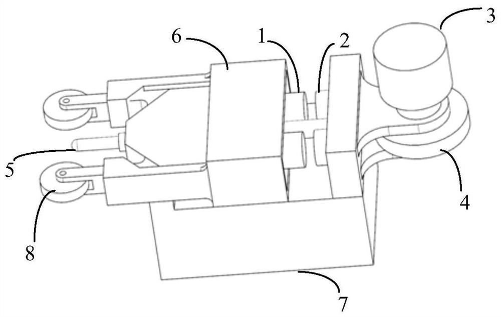
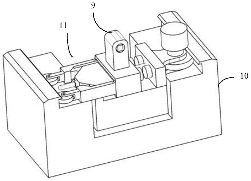
[0025] The present invention provides a magnetic self-driven trolley, which is characterized in that: it includes a vehicle body; a guide seat 6 fixedly installed on the vehicle body; a sliding assembly capable of moving in the guide seat 6, and the sliding assembly includes a relatively fixed sliding electromagnetic Iron 1, driven wheel 8 and measuring rod 5; The other end of described sliding electromagnet 1 is provided with driving assembly, and described driving assembly comprises the driving electromagnet 2 that attracts or repels mutually with described sliding electromagnet, and with all The driving electromagnet 2 is a relatively fixed driving wheel 4, and a driving motor 3 for driving the driving wheel 4; the driving wheel...


PUM


Abstract

The embodiment of the present invention provides a magnetic force self-driven trolley, which is characterized in that: it includes a vehicle body; a guide seat (6) fixedly installed on the vehicle body; a sliding assembly capable of moving in the guide seat (6), and the sliding assembly includes The sliding electromagnet (1), the driven wheel (8) and the measuring rod (5) are relatively fixed in position; the other end of the sliding electromagnet (1) is provided with a driving assembly, and the driving assembly includes a The driving electromagnet (2) that iron attracts or repels each other, and the driving wheel (4) that is relatively fixed with the position of the driving electromagnet (2), and the driving motor (3) that is used to drive the driving wheel (4) The drive wheel (4) and the driven wheel (8) and the measuring rod (5) are located at the two ends of the vehicle body respectively; by measuring the measuring rod (5) in the sliding assembly during the movement of the magnetic self-driven dolly, Contact with the side wall of the guide rail to obtain the groove width and straightness of the guide rail in real time.

Description

technical field [0001] The invention can be used for precise measurement of the straightness of the bottom surface and the side of the guide rail, and the groove width of the guide rail, can realize automatic detection and data feedback, and is specifically applied to the fields of precision and ultra-precision processing and assembly of the guide rail. Background technique [0002] Guide rail, or slide rail, is a device formed of metal materials or other materials that can guide, fix, carry mobile equipment and reduce friction. It can be used to guide and fix special equipment such as mechanical parts and instruments. Such as figure 2 The guide rail shown can be connected with special equipment or other mechanical parts through L-shaped sliders. It has a simple structure and can withstand higher loads than linear bearings in performance. It can also carry a certain torque. High-precision linear movement can be realized. The straightness and section width error of the guid...

Claims


Application Information

Patent Timeline
Patent Type & Authority Patents(China)
IPC IPC(8): B62D63/02G01B11/02G01B11/26G01B11/30
CPCB62D63/02G01B11/02G01B11/26G01B11/30
Inventor 金路李建华穆英娟潘华东张大伟杨斌梁星慧
Owner SHANGHAI SPACE PRECISION MACHINERY RES INST
Why Eureka
Try Eureka