High-speed sailing vehicle combing micro-bubble drag reduction technology and groove surface turbulence drag reduction technology

A technology of aircraft and micro-bubbles, applied in the direction of hydrodynamic characteristics/hydrostatic characteristics, ships, hulls, etc., to reduce resistance, improve drag reduction efficiency, and improve rapidity

Inactive Publication Date: 2019-09-06
WUHAN UNIV OF TECH
View PDF6 Cites 5 Cited by
  • Summary
  • Abstract
  • Description
  • Claims
  • Application Information

AI Technical Summary

Problems solved by technology

[0005] The technical problem to be solved by the present invention is to provide a combination of micro-bubble drag reduction technology and groove surface turbulent drag reduction technology for the vacancy of the combination of micro-bubble drag reduction and groove surface turbulent drag reductio

Method used


Image

  • High-speed sailing vehicle combing micro-bubble drag reduction technology and groove surface turbulence drag reduction technology
  • High-speed sailing vehicle combing micro-bubble drag reduction technology and groove surface turbulence drag reduction technology

Examples


Embodiment Construction

[0017] In order to have a clearer understanding of the technical features, purposes and effects of the present invention, the specific implementation manners of the present invention will now be described in detail with reference to the accompanying drawings.

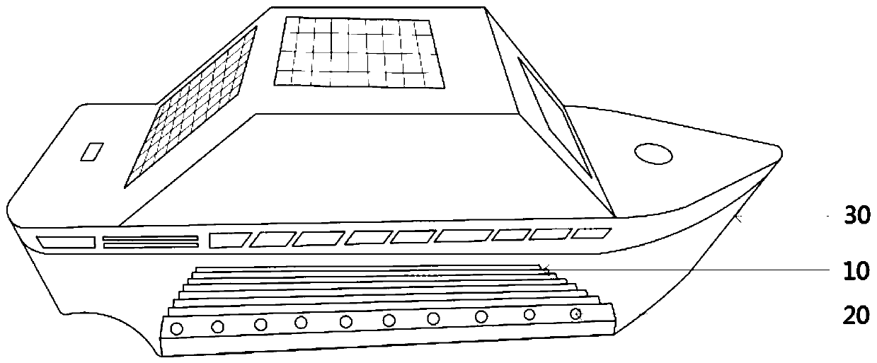
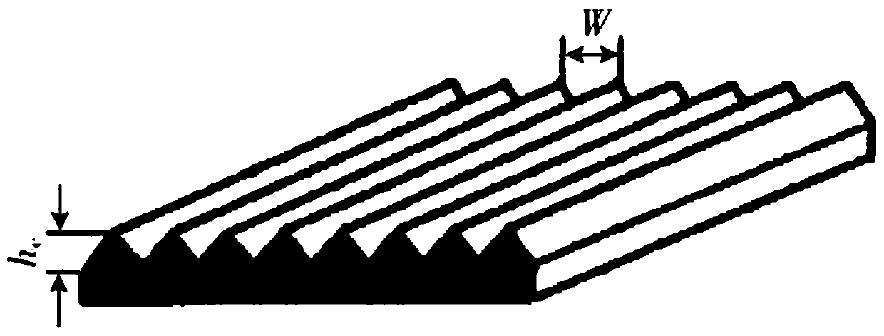
[0018] Such as figure 1 As shown, it is a high-speed aircraft combined with microbubble drag reduction technology and groove surface turbulent drag reduction technology in a preferred embodiment of the present invention. The bottom surface of the hull 30 of the high-speed aircraft is provided with several parallel grooves along the length of the ship. 10. The cross section of the groove 10 is square, U-shaped or V-shaped, and the groove height hc of the groove 10 is equal to the groove width W, and the range of the groove width W is: 25 μm≤W≤300 μm. The high-speed aircraft also includes a micro-bubble generating device arranged in the engine room. The micro-bubble generating device generates bubbles and transports them ...


PUM


Abstract

The invention relates to a high-speed sailing vehicle combining a micro-bubble drag reduction technology and a groove surface turbulence drag reduction technology. The high-speed sailing vehicle is characterized in that a plurality of parallel grooves which are parallel to each other are formed in the bottom surface of a ship body in the length direction of the ship body, the cross sections of thegrooves are square, U-shaped or V-shaped, the groove height hc of the grooves is equal to the width W of the grooves, the high-speed sailing vehicle further comprises a micro-bubble generation devicearranged inside a cabin, the micro-bubble generation device generates air bubbles and conveys the air bubbles to the bottom of the ship body through air pipes, the air pipes are laid inside the grooves, and exhaust holes are uniformly formed in the length direction of the grooves. According to the high-speed sailing vehicle, the grooves are designed at the bottom of the ship body, and the purposeof reducing the resistance is achieved by changing the flowing structure of the bottom layer of the boundary layer; and meanwhile, the exhaust holes are formed in the grooves, and the bubbles are discharged out of the surfaces of the grooves to generate a dispersed fine air curtain so that the resistance can be further reduced, the combined drag reduction effect can be achieved through the effective combination of the two drag reduction technologies, the drag reduction efficiency is improved, and then the rapidity of the sailing vehicle is improved.

Description

technical field [0001] The invention relates to the technical field of aircraft drag reduction design, in particular to a high-speed aircraft combined with microbubble drag reduction technology and groove surface turbulent drag reduction technology. Background technique [0002] Micro-bubble drag reduction can also be called air layer and cavitation drag reduction. It is to create air bubbles on the surface of objects to achieve the effect of drag reduction and noise reduction. That is, the air is released through the small holes in the air pipeline laid around the aircraft to generate diffuse air. A very thin air curtain, which can not only effectively reduce the frictional resistance between the hull and the water, but also isolate the radiation of the hull noise source to the water, so as to achieve the purpose of reducing drag and noise. The principle is to use the characteristics of small friction and easy deformation of air bubbles to adjust the underlying flow structu...

Claims


Application Information

Patent Timeline
IPC IPC(8): B63B1/38
CPCB63B1/38B63B2001/387Y02T70/10
Inventor 朱汉华李昕隆梁应超王兆隆费宇轩
Owner WUHAN UNIV OF TECH
Why Eureka
Try Eureka