Axial force self-balance type four-screw mechanical device with gas thrust bearings

A thrust bearing and mechanical device technology, applied in the field of compressors and expanders, can solve the problems of reduced friction, low bearing capacity, large friction loss, etc., and achieve the effect of simplifying the structure of the unit

Active Publication Date: 2019-09-06
XI AN JIAOTONG UNIV
View PDF6 Cites 2 Cited by
  • Summary
  • Abstract
  • Description
  • Claims
  • Application Information

AI Technical Summary

Problems solved by technology

However, the viscosity of liquid lubrication is relatively large, resulting in large friction loss
The gas bearing is a sliding bearing with gas as a lubricant. It uses the transmission, adsorption and compressibility of the gas to make it between the friction pairs under the action of hydrodynamic pressure effect, static pressure effect and extrusion effect. Form a complete air film to support the load and reduce friction. It has the advantages of low friction torque, small loss, wide temperature range, low noise, and can work at extremely high speed, but its bearing capacity is low.

Method used


Image

  • Axial force self-balance type four-screw mechanical device with gas thrust bearings
  • Axial force self-balance type four-screw mechanical device with gas thrust bearings
  • Axial force self-balance type four-screw mechanical device with gas thrust bearings

Examples


Embodiment 1

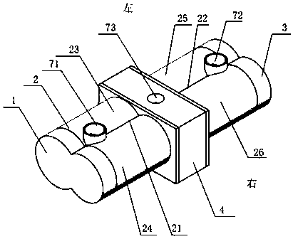
[0057] Taking the gas thrust bearing as an example, the gas static pressure thrust bearing is used, such as Figure 7 shown.

[0058] Aerostatic thrust bearings are one type of sliding bearings. When the gas enters the first working chamber 10 of the gas thrust bearing through the second exhaust hole 82, on the one hand, a layer of lubricating gas film with a certain load and rigidity will be formed in the gap between the bearing and the shaft. The supporting effect makes the shaft float in the bearing. On the other hand, the gas enters the second working chamber 11 of the gas thrust bearing through the orifice of the gas thrust bearing. The pressure increases and the flow rate decreases. The third exhaust hole 83 merges into the exhaust port 73 and is discharged together with the gas directly flowing into the exhaust port 73 , and forms a lubricating air film with a certain load and rigidity in the second working chamber 11 to bear the axial force. In the exhaust seat, the ...

Embodiment 2

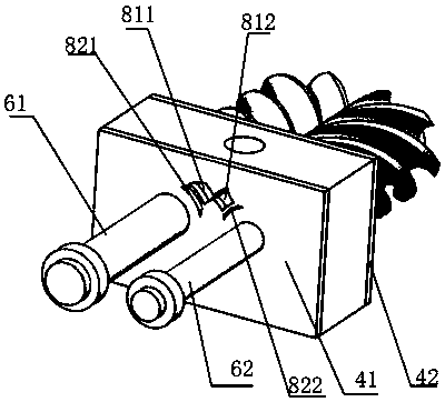
[0060] Taking the gas thrust bearing as an example, the gas dynamic pressure thrust bearing is used, such as Figure 8 shown.

[0061]The dynamic pressure bearing is mainly composed of two parts: a wedge structure and a fluid lubricating film. When the gas enters the first working chamber 10 of the gas thrust bearing through the second exhaust hole 82, the gas enters the second working chamber 11 from the first working chamber 10 through the gap between the inner ring of the bearing and the first rotating shaft 61 / second rotating shaft 62 , and then flow into the exhaust port 73 through the third exhaust hole 83 under the action of the pressure difference, and be discharged together with the gas directly flowing into the exhaust port 73 . Due to the certain viscosity of the gas, the gas is compressed when it enters the reserved wedge-shaped area, and the compressed gas will generate axial pressure in the second working chamber 11 and generate supporting capacity. In the exha...


PUM


Abstract

The invention discloses an axial force self-balance type four-screw mechanical device with gas thrust bearings. The mechanical device adopts four screws which are symmetrically arranged and have opposite thread turning directions, the screws in the same housing are engaged with each other by pairs, and the thread turning directions of the screws on the same shaft but different housings are opposite, so that in the normal running process of the mechanical device, axial force on two rotors is basically countered, and the self-balance of the axial force is realized; and two symmetrical thrust bearings are arranged on each shaft, so that remaining axial force on each shaft can be bore by the two symmetrical thrust bearings, small absolute value axial force which cannot be fully self-balanced can be bore, the bi-directional thrust of an exhaust-end bearing of the four-screw mechanical device is realized, and friction losses can be effectively reduced. The gas thrust bearings and the four-screw mechanical device are combined together, the axial force is effectively balanced, the working efficiency is increased, and at the same time, the working stability of a compressor or an expander isimproved.

Description

[0001] 【Technical field】 [0002] The invention belongs to the technical field of compressors and expanders, and relates to a self-balancing axial force four-screw mechanical device with a gas thrust bearing. [0003] 【Background technique】 [0004] Screw machinery mostly adopts twin-screw rotors, and the so-called screw compressor or expander refers to the twin-screw compressor or expander. On the rotor of a twin-screw machine, there are radial and axial forces acting on it. The radial force is generated due to the different pressures on both sides of the rotor, and its magnitude is related to the rotor diameter, length-to-diameter ratio, internal pressure ratio and operating conditions. Since one end of the rotor is the suction pressure, the other end is the exhaust pressure, and one rotor drives the other, an axial force is generated. The magnitude of the axial force is a function of the rotor diameter, internal pressure ratio and operating conditions. . [0005] In a twi...

Claims


Application Information

Patent Timeline
Patent Type & Authority Applications(China)
IPC IPC(8): F04C18/16F04C29/00F04C29/12F01C1/16F01C21/00F01C21/02F01C21/10
CPCF01C1/082F01C1/165F01C21/003F01C21/02F01C21/10F04C18/082F04C18/165F04C29/0021F04C29/12F04C2240/30F04C2240/54
Inventor 王莹邢子文王闯张震何志龙
Owner XI AN JIAOTONG UNIV
Why Eureka
Try Eureka