
Multi-pass high-speed cutting test device and method based on Hopkinson pressure bar loading

A Hopkinson compression bar and high-speed cutting technology, which is applied in the field of metal cutting, can solve problems such as the complexity of the test process, test result errors, and control tests, and achieve the goal of optimizing the high-speed cutting test process, reducing test errors, and shortening the duration. Effect

Pending Publication Date: 2019-09-06
QINGDAO TECHNOLOGICAL UNIVERSITY
View PDF0 Cites 1 Cited by
  • Summary
  • Abstract
  • Description
  • Claims
  • Application Information

AI Technical Summary

Problems solved by technology

However, the current device only has a single cutting pass, and it is impossible to conduct multiple comparative tests at different cutting speeds or control tests at the same cutting speed at the same time.
Moreover, in the actual operation process, the test process will be complicated due to the test requirements of changing the cutting speed, or the test results of the same cutting speed will be caused by the error of the test results due to the deviation of the workpiece clamping.

Method used


Image

  • Multi-pass high-speed cutting test device and method based on Hopkinson pressure bar loading
  • Multi-pass high-speed cutting test device and method based on Hopkinson pressure bar loading
  • Multi-pass high-speed cutting test device and method based on Hopkinson pressure bar loading

Examples


Embodiment 1

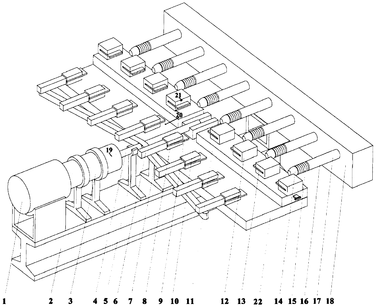
[0043] Such as figure 1As shown, the entire cutting test device of this embodiment is built based on the improved Hopkinson compression bar loading technology, and the entire device is distributed axisymmetrically, including the Hopkinson compression bar power mechanism (including the light air gun 1, the accelerating tube 3 and the incident rod 4), cutting mechanism 6, cutting bracket 7, workpiece clamping mechanism 12, guiding mechanism, trapping mechanism 16, support 2 and high-precision positioning platform 11, arranged along the symmetrical axis of the entire device in sequence; cutting mechanism 6, workpiece There are multiple sets of clamping mechanism 12 and capture mechanism 16. In this embodiment, eight groups are used as an example to introduce, with four groups on each side. Arranged in sequence.

[0044] The Hopkinson pressure rod power mechanism and the cutting bracket 7 are fixedly installed on the support 2, and eight sets of workpiece clamping mechanisms 12 a...

Embodiment 2

[0065] This embodiment provides a multi-pass high-speed cutting test method based on Hopkinson compression bar loading.

[0066] As a preferred embodiment, the method is implemented based on a multi-pass high-speed cutting test device. The device is equipped with multiple sets of cutting tools, which can adjust the arrangement of the cutting mechanism and obtain multiple sets of different cutting speeds at the same time, thereby achieving different passes. Cutting comparison test at different speeds.

[0067] The method mainly includes the following steps:

[0068] (1) Install the test device described above;

[0069] (2) Install the workpiece on the workpiece clamping mechanism to ensure that the tool and the workpiece are cut at a perpendicular angle, and at the same time move the incident rod axially to ensure that the two groups of workpieces closest to the axis are as close as possible to the two groups of tools at the front end; gradually adjust the height The precisio...

Embodiment 3

[0075] Install the entire test device, the specific implementation of the test steps are as follows:

[0076] 1. Combine figure 1 In the structure shown, eight sets of YW material cutters 9 with a thickness of 6mm, a rake angle of 0%, and a relief angle of 15° are installed on the front end of the cutting mechanism 6 through the tool clamping mechanism 8 . The incident rod 4 is erected in the guide groove 10 on the support 2, and one end is fixedly connected with the cutting support 7, and ensures that the other end is facing the outlet of the light air gun 1, and keeps a distance of about 100 mm from the muzzle.

[0077] 2. Install the eight sets of workpiece clamping mechanisms 12 on the high-precision positioning platform 11 and distribute them symmetrically with the axis of the incident rod 4 as the reference. Install eight Ti6Al4V material workpieces 13 with a length of 50 mm, a width of 40 mm, and a thickness of 3 mm on the workpiece clamping mechanism 12, and adjust th...


PUM


Abstract

The invention discloses a multi-pass high-speed cutting test device and method based on Hopkinson pressure bar loading. The device comprises a Hopkinson pressure bar power mechanism, cutting mechanisms, cutting brackets, workpiece clamping mechanisms, a guiding mechanism, collecting mechanisms, a support, and a high-precision positioning platform that are arranged successively along the symmetry axis of the whole device. Multiple groups of cutting mechanisms, workpiece clamping mechanisms, and collecting mechanisms are arranged respectively. The Hopkinson pressure bar power mechanism includesa light air gun and an incident rod; the two sides of the incident rod are fixedly connected with the cutting brackets; and the cutting mechanisms are installed on the cutting brackets symmetrically.The light air gun fires a bullet to impact the incident rod so as to move forward. The cutting brackets fixedly connected to the incident rod drive the multiple groups of cutting mechanisms simultaneously to move forward; and cutters arranged at the front ends of the cutting mechanisms cut workpieces fixed on the workpiece clamping mechanisms successively until the last two groups are cut completely. Therefore, cutting comparison testing at different speeds at different passes can be realized.

Description

technical field [0001] The invention belongs to the technical field of metal cutting, in particular to a multi-pass high-speed cutting test device and method based on Hopkinson pressure bar loading. Background technique [0002] As an advanced and practical processing and manufacturing technology, high-speed cutting technology has become more and more widely used in machinery manufacturing, mold processing, aerospace industry and other fields, and has unique advantages in processing technology and precision. However, the research on the key technology of high-speed cutting mainly focuses on the technical improvement and structural innovation of high-speed cutting machine tools, and the research on the mechanism of high-speed cutting is still mainly in the stage of theory and simulation analysis. The mechanism of cutting deformation and the changing rules of cutting temperature, tool wear and cutting force. [0003] High-speed cutting tests are currently mainly carried out o...

Claims


Application Information

Patent Timeline
Patent Type & Authority Applications(China)
IPC IPC(8): G01N3/58G01N3/02G01P3/38
CPCG01N3/58G01N3/02G01P3/38G01N2203/0053
Inventor 李云凯王优强谢奕浓罗恒于晓菅光霄
Owner QINGDAO TECHNOLOGICAL UNIVERSITY
Learn More