
NVMe SSD reading speed and optical fiber interface speed adaptive matching method

A technology of adaptive matching and optical fiber interface, which is applied in the direction of instrumentation, electrical digital data processing, etc., can solve the problem of occupying too much data cache resources, achieve the effect of reducing the demand for cache resources and saving the usage of BlockRam cache resources

Active Publication Date: 2019-09-06
HARBIN INST OF TECH
View PDF4 Cites 6 Cited by
  • Summary
  • Abstract
  • Description
  • Claims
  • Application Information

AI Technical Summary

Problems solved by technology

[0004] The purpose of the present invention is: in view of the problem that the NVMe SSD reading speed control method occupies more data cache resources in the FPGA, a method for adaptively matching the NVMe SSD reading speed and the optical fiber interface speed is proposed

Method used


Image

  • NVMe SSD reading speed and optical fiber interface speed adaptive matching method
  • NVMe SSD reading speed and optical fiber interface speed adaptive matching method
  • NVMe SSD reading speed and optical fiber interface speed adaptive matching method

Examples


specific Embodiment approach 1

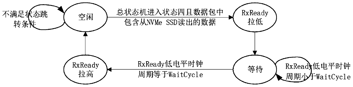
[0033] Specific implementation mode one: refer to figure 1 Specifically illustrate this embodiment, in this embodiment, a kind of NVMe SSD reading speed and optical fiber interface speed self-adaptive matching method, comprise the following steps: first FPGA receives the data packet of reading data that returns from NVMe SSD, then RxReady signal is pulled low for five clock cycles.

[0034] When an NVMe storage device executes a read command, the speed of the fiber data interface is slower than that of the NVMe SSD. In order to match the speed of the NVMe SSD data read with the speed of the fiber data interface, the data read speed of the NVMe SSD must be reduced .

[0035] A common method is to control the read data speed of NVMe SSD by reducing the size of each NVMe read command and inserting a waiting interval between adjacent read commands. This method is limited by the logical block size (512Byte or 4KByte) of NVMe SSD, and can only control the average speed at which NV...

specific Embodiment approach 2

[0041] Embodiment 2: This embodiment is a further description of the adaptive matching method for NVMe SSD reading speed and fiber interface speed described in Embodiment 1. The difference between this embodiment and Embodiment 1 is that the RxReady The signal is pulled low by the state machine.

specific Embodiment approach 3

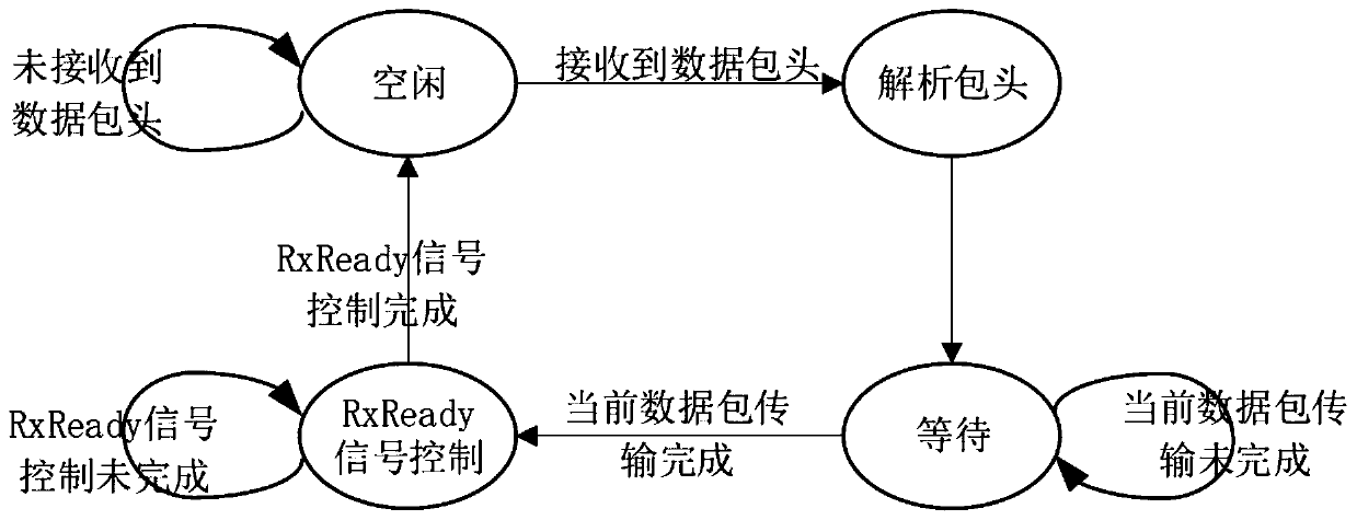
[0042] Embodiment 3: This embodiment is a further description of the method for adaptively matching the reading speed of an NVMe SSD and the speed of an optical fiber interface described in Embodiment 2. The difference between this embodiment and Embodiment 2 is the state The state of the machine includes: idle state, parsing packet header state, waiting state and RxReady signal control state.


PUM


Abstract

The invention discloses an NVMe SSD reading speed and optical fiber interface speed adaptive matching method in the technical field of data storage. In order to solve the problem that an NVMe SSD reading speed control method occupies more data cache resources in an FPGA in the prior art, the method comprises the following steps that firstly, the FPGA receives a data packet of reading data returnedfrom an NVMe SSD, and then an RxRead signal is pulled down by five clock periods. The invention controls the sending speed of a data packet when the NVMe SSD reads the data by using a RxReady signalof an AXI-Stream data receiving interface on a PCIe hard core, so that the NVMe SSD data reading speed matches the optical data interface speed. A complete reading command does not need to be split into a plurality of sub-commands. Enough time sequence allowance is reserved for the data packet receiving and analyzing process and development is easy. In addition, the method can reduce the requirement for cache resources in the data reading process, 50% of Block Ram cache resources and 92% of Block Ram cache resources are saved when the size of a logic block of the NVMe SSD is 512 Byte and 4 KByte respectively, and the method can be widely applied to the technical field of data storage.

Description

technical field [0001] The invention relates to the technical field of data storage, in particular to a method for adaptively matching the reading speed of an NVMe SSD and the speed of an optical fiber interface. Background technique [0002] NVMe SSD is a new-generation storage device that has emerged in recent years. With the help of the high transmission speed of the PCIe bus, it can achieve a data reading speed of more than 2GB / s. NVMe SSD is small in size and low in power consumption. Together with FPGA, it can form a miniaturized and portable optical fiber data storage device. The device uses the optical fiber interface to transmit the data in the storage device to the data processing device. This X4 optical fiber interface can reach a total data transmission rate of 12.5Gbps. [0003] When an NVMe storage device executes a read command, the speed of the fiber data interface is slower than that of the NVMe SSD. Therefore, a method must be used to match the read speed ...

Claims


Application Information

Patent Timeline
Patent Type & Authority Applications(China)
IPC IPC(8): G06F13/16
CPCG06F13/16
Inventor 张京超乔立岩孟凡廓朱凯晖刘旺彭喜元
Owner HARBIN INST OF TECH
Learn More