Local constraint damping plate vibration suppression analysis method

A technology of restraint damping and vibration suppression, applied in the field of vibration reduction and noise reduction, can solve problems such as increased computing cost, incompatibility, and increased computing scale, and achieve the effects of strong application value, easy implementation, and simple principle.

Inactive Publication Date: 2019-09-06
SHENYANG INST OF AUTOMATION - CHINESE ACAD OF SCI
View PDF4 Cites 4 Cited by
  • Summary
  • Abstract
  • Description
  • Claims
  • Application Information

AI Technical Summary

Problems solved by technology
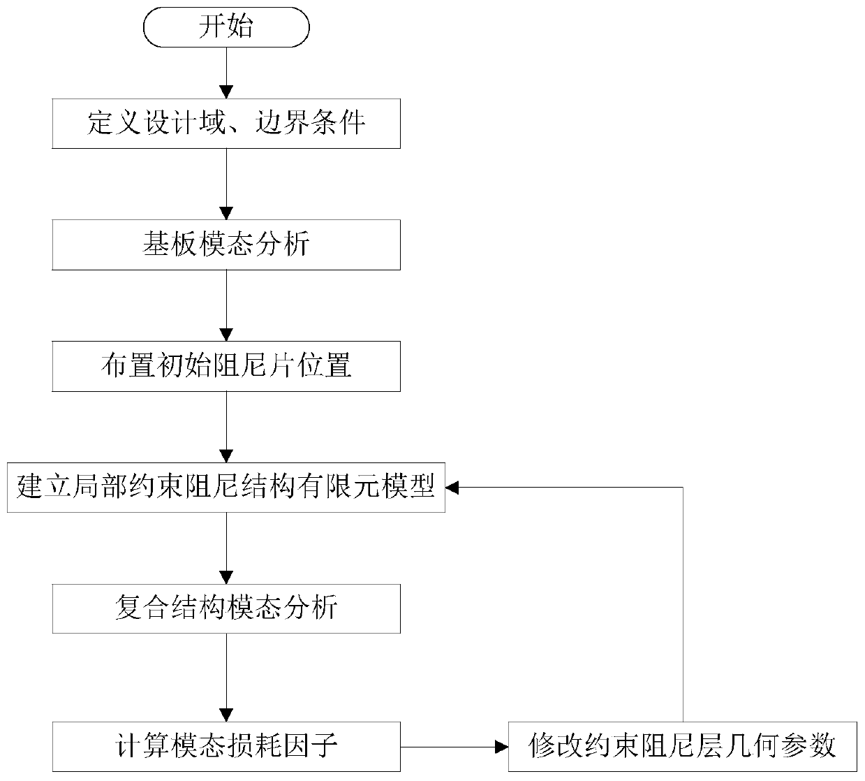
Although some progress has been made in traditional locally constrained damping structural analysis and optimization methods, there are still many challenging problems to be solved
First of all, from the perspective of structural topology expression, the continuous size optimization method adopts an implicit expression to describe the structural topology, which is obviously different from the modern method of using geometric elements (such as points, straight line segments, and Bezier curves) to express structural geometric and topological information. Computer Aided Design (CAD) technology is not compatible
Secondly, traditional topology optimization methods often use continuous optimization algorithms to deal with discrete 0-1 optimization problems. In the optimization process, some special processing methods need to be used to avoid the appearance of gray-scale units and checkerboard grids, which increases computational costs, reduces computational efficiency, and converges. rate
For the analysis and optimization of the geometric parameters of the constrained damping structure, when the geometric parameters of the constrained damping change, it is usually necessary to re-mesh to adapt to the change of the boundary of the constrained damping layer; for the topology optimization of the constrained damping structure, the optimization model and the finite The element models are coupled to each other, and the topology optimization design variables depend on the number of finite element grids. Although the finer finite element grid can improve the calculation accuracy of finite elements, it will lead to an increase in the calculation scale of the optimization problem.

Method used


Image

  • Local constraint damping plate vibration suppression analysis method
  • Local constraint damping plate vibration suppression analysis method
  • Local constraint damping plate vibration suppression analysis method

Examples


Embodiment Construction

[0038] The present invention will be further described in detail below in conjunction with the accompanying drawings and embodiments.

[0039] In order to make the above objects, features and advantages of the present invention more comprehensible, specific implementations of the present invention will be described in detail below in conjunction with the accompanying drawings. In the following description, numerous specific details are set forth in order to provide a thorough understanding of the present invention. However, the present invention can be implemented in many other ways different from those described here, and those skilled in the art can make similar improvements without violating the connotation of the invention, so the present invention is not limited by the specific implementation disclosed below.

[0040] Unless otherwise defined, all technical and scientific terms used herein have the same meaning as commonly understood by one of ordinary skill in the techni...


PUM


Abstract

The invention relates to a local constraint damping plate vibration suppression analysis method, which comprises the following steps of: obtaining an area with dense modal strain energy distribution of a thin plate as a target area through finite element modal analysis, and determining a central position of initial distribution of constraint damping plates; describing geometric information of theconstrained damping plate through an explicit geometric description function; performing grid division on the constrained damping plate structure; establishing a stiffness matrix and a mass matrix ofthe entity constraint damping unit, and obtaining the stiffness matrix and the mass matrix of the composite unit cut by the constraint damping fin boundary; assembling the stiffness matrix and the mass matrix of each composite unit to obtain an integral stiffness matrix and an integral mass matrix, and establishing a finite element dynamic model of the constrained damping plate to obtain a modal loss factor of the constrained damping plate. Parameter analysis and optimization of the local constraint damping thin plate structure can be achieved, and grid redivision is not needed during parameter analysis and optimization; the method is simple in principle, easy to implement and high in application value.

Description

technical field [0001] The invention relates to the technical field of vibration reduction and noise reduction, in particular to a vibration suppression analysis method of a locally constrained damping plate. Background technique [0002] Vibration and noise reduction technology has always been an important topic in the field of engineering design. The surface treatment technology based on viscoelastic constrained damping materials can not only effectively suppress the structural broadband vibration noise, but also has the characteristics of not changing the original structure and being easy to implement. It is an economical, reliable and effective method. Therefore, it is widely used in the fields of aviation, aerospace, ships and vehicles. In the traditional vibration damping design of thin-walled structures, the viscoelastic constrained damping material is generally laid on the surface of the structure completely, which increases the additional mass of the entire structu...

Claims


Application Information

Patent Timeline
Patent Type & Authority Applications(China)
IPC IPC(8): G06F17/50
CPCG06F30/23
Inventor 骆海涛陈荣富佳武廷课
Owner SHENYANG INST OF AUTOMATION - CHINESE ACAD OF SCI
Why Eureka
Try Eureka