Cooling system for data center system and data center system

A technology for cooling systems and data centers, which is applied in cooling/ventilation/heating transformation, electrical components, electrical equipment construction parts, etc., and can solve the problems of low cooling efficiency, chaotic air flow in data centers, and non-energy-saving air supply and return methods in data centers, etc. problems, to achieve the effect of improving cooling efficiency, reducing waste of resources, and reducing mixing of hot and cold air

Pending Publication Date: 2019-09-06
HEBEI QINHUAI DATA CO LTD
View PDF0 Cites 4 Cited by
  • Summary
  • Abstract
  • Description
  • Claims
  • Application Information

AI Technical Summary

Problems solved by technology

[0006] Therefore, the technical problem to be solved by the present invention is that the existing air supply and return methods of the data center are not energy-saving, and when the a

Method used


Image

  • Cooling system for data center system and data center system
  • Cooling system for data center system and data center system
  • Cooling system for data center system and data center system

Examples


Embodiment 1

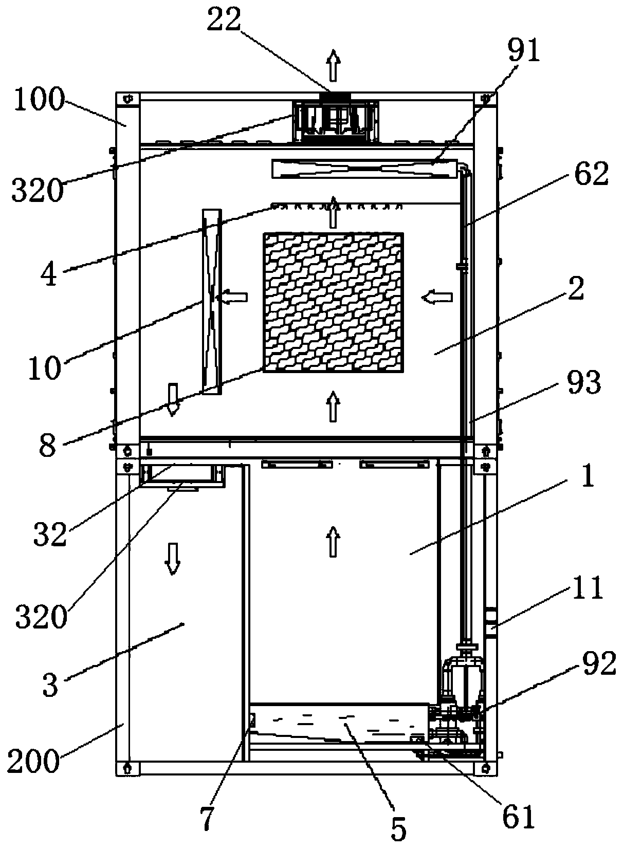
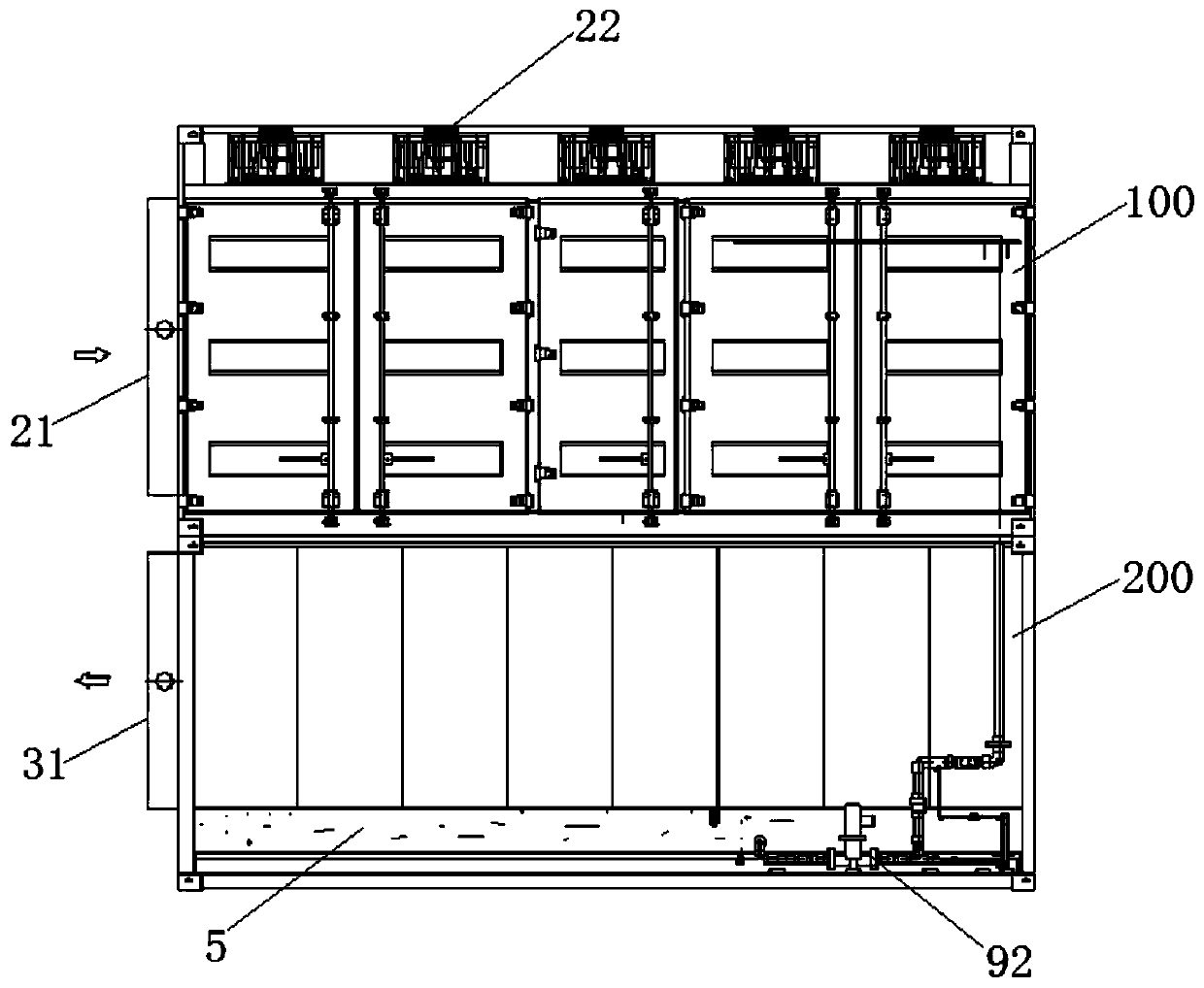
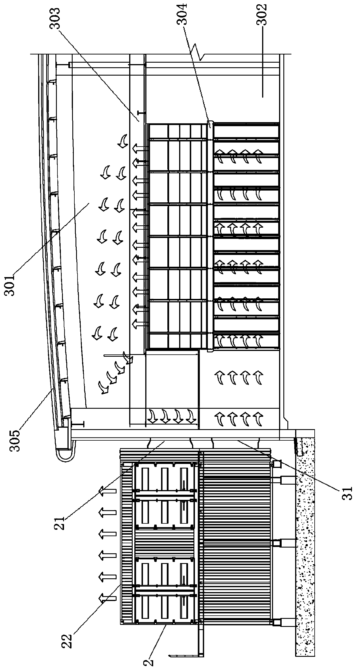
[0061] This embodiment provides a cooling system for a data center system, such as image 3 As shown, the cooling system for the data center system is set inside the computer room (not shown in the figure) of the data center system. The computer room is located on one side of the cooling system and has a hot return air layer 301 and a cold pool layer 302 distributed up and down and connected. , several cabinets 304 are arranged side by side in the cold pool layer 302 . Such as figure 1 As shown, the cooling system for the data center system includes an upper shell 100 and a lower shell 200. In this embodiment, the upper shell 100 and the lower shell 200 respectively adopt a container shell, and the inner cavity of the lower shell 200 is spaced Out of the air inlet chamber 1 and the air supply chamber 3 on the left and right sides, the air inlet chamber 1 is located on the side wall of the lower casing 200 to open a new air outlet 11, and the new air outlet 11 can adopt square...

Embodiment 2

[0073] This embodiment provides a data center system, such as image 3 As shown, it includes a computer room (not shown in the figure), several cabinets 304 and the cooling system for the data center system in Embodiment 1. Wherein, the machine room cover is arranged on the outside of the cabinet 304 and the cooling system, and the interlayer suspended ceiling 303 is arranged between the heat return air layer 301 and the cold pool layer 302 in the machine room, and the interlayer suspended ceiling 303 and the cabinet 304 are separated by a certain distance. Several passages (not shown in the figure) are evenly distributed, and the hot air emitted by the cabinet 304 naturally rises to the heat return air layer 301 through the passages, such as image 3 As shown, when the cooling system is only installed on one side of the machine room, the height of the top of the hot return air layer 301 gradually increases from the side close to the cooling system to the other side of the mac...


PUM


Abstract

The invention provides a cooling system for a data center system and the data center system. A mixed air chamber and a hot return air layer are connected through a return air port and are arranged inthe same layer; an air supply chamber and a cold pool layer are connected through an air supply port and are arranged in the same layer; a lower air supply chamber is formed in a machine room of the cooling system to flow to the cold pool layer; the cold pool layer flows to the hot return air layer from bottom to top; an upper hot return air layer flows to the mixed air chamber; the mixed air chamber exchanges heat and cools the indoor return air and then flows to a circulating cooling system of the air supply chamber from top to bottom; air current circulation is implemented by fully utilizing the air autoconvection mode of natural descending of cold air and natural ascending of hot air, thereby reducing the mixing of cold and hot air, improving the refrigerating efficiency and recyclingof energy. A diffuse type air supply end is disposed in the air supply port so that the cold air is diffused to the whole cold pool layer in a manner of diffusion, and the negative pressure problem caused by the excessive wind speed of the proximal cabinet of the air supply port and the problem of insufficient cold air volume of the remote cabinet of the air supply port are solved.

Description

technical field [0001] The invention belongs to the technical field of refrigeration, and in particular relates to a cooling system for a data center system and the data center system. Background technique [0002] Refrigeration devices are more and more widely used in daily life. The indoor air temperature is adjusted through refrigeration devices, but pure mechanical refrigeration consumes a lot of energy and has a low energy efficiency ratio. Fresh air direct evaporative cooling has high energy efficiency, but the temperature and humidity control is unstable, and the temperature range that can be adjusted is small. Using natural cooling, the indoor temperature cannot be reduced to the required temperature in hot seasons, especially in indoor heat dissipation temperatures such as data center computer rooms. And in areas that need to be cooled all year round to maintain a certain temperature, natural cooling alone cannot meet the requirements, and only the temperature diffe...

Claims


Application Information

Patent Timeline
IPC IPC(8): H05K7/20
CPCH05K7/20745H05K7/20827
Inventor 居静王剑刘治国
Owner HEBEI QINHUAI DATA CO LTD
Why Eureka
Try Eureka