Supercharge Your Innovation With Domain-Expert AI Agents!

Vertical extrusion dewatering machine for sludge

A squeeze dehydrator and sludge technology, applied in water/sludge/sewage treatment, sludge treatment, chemical instruments and methods, etc., can solve the problems of inconvenient sludge removal, increased equipment volume, and increased equipment cost , to achieve the effect of improving operating efficiency, compact dehydration components, and reducing performance requirements

Active Publication Date: 2019-09-10
GUANGDONG HANDSOME INTELLIGENT EQUIP CO LTD
View PDF12 Cites 0 Cited by
  • Summary
  • Abstract
  • Description
  • Claims
  • Application Information

AI Technical Summary

Problems solved by technology

Existing sludge dewatering devices are usually horizontal and occupy a large area, and the sludge is easy to flow downwards and accumulate under the action of its own gravity, which affects the extrusion effect, and it is often difficult to reduce the moisture content of the sludge to meet the predetermined requirements
At present, there are also some vertical sludge dewatering devices on the market, which arrange the dewatering components vertically. Each dewatering component includes an upper mold and a lower mold, and a main drive device is used to press down the uppermost dewatering component. The upper mold and the lower mold of each dewatering assembly are close together to squeeze and dewater the sludge. This vertical sludge dewatering device can effectively reduce the floor space and improve the uniformity of sludge distribution. To a certain extent However, since these existing vertical sludge dewatering devices only use one main drive device to drive multiple dewatering components, on the one hand, the main drive device needs to simultaneously drive multiple dewatering components to squeeze the sludge. Therefore, a large driving force is required, and the requirements for the main driving device are high, which will increase the equipment cost and increase the volume. There is also a limit to the number of dehydration components, which will limit the production efficiency accordingly, and it is difficult to ensure Uniform force will affect the dehydration effect. On the other hand, in order to avoid sludge leakage, it is often necessary to set a storage tank on the lower mold to accommodate the sludge, so that the upper mold can move in the storage tank to clean the sludge in the storage tank. Squeeze and dewater, so that the dehydrated sludge will also be located in the holding tank, which is inconvenient to take out the dehydrated sludge. It is often necessary to additionally set up a driving structure that drives the housing of the housing tank to move the housing of the chamber. From the lower mold, the structure is more complex, which will increase the cost of equipment and increase the volume of equipment
In addition, the water squeezed out by the existing sludge dewatering equipment is often directly drained away, which is easy to cause pollution to the environment

Method used


Image

  • Vertical extrusion dewatering machine for sludge
  • Vertical extrusion dewatering machine for sludge
  • Vertical extrusion dewatering machine for sludge

Examples


Embodiment Construction

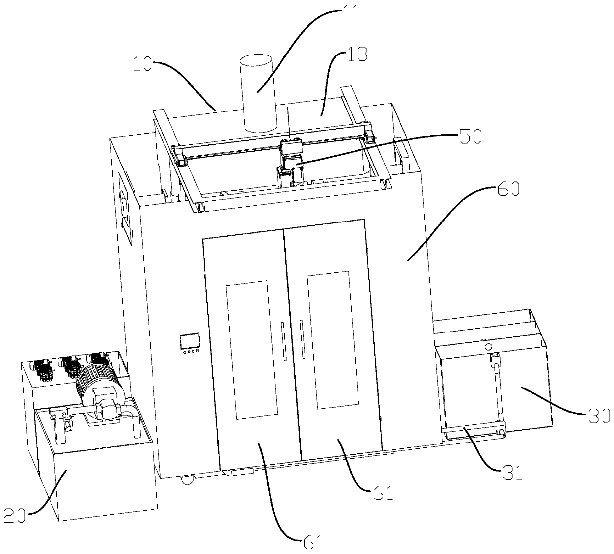
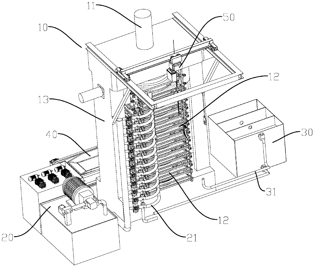
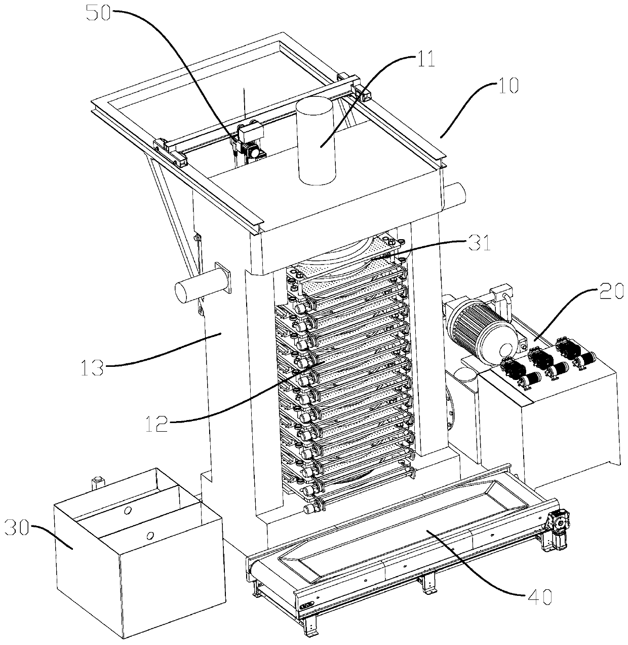
[0028] refer to Figure 1 to Figure 8 , a preferred embodiment of the present invention, a vertical sludge extrusion dewatering machine, comprising: a main body 10, including a first driving device 11 and several dewatering assemblies 12 arranged vertically; each dewatering assembly 12 includes an upper mold 121 And the lower mold 122, after the upper mold 121 and the lower mold 122 are closed, an extrusion chamber for holding the sludge can be formed. The upper mold 121 is provided with a piston chamber 123 and an extrusion part 124, and the piston chamber 123 can be connected with the outside world. The fluid power source is connected, and the extrusion part 124 has a piston part that is slidably arranged in the piston chamber 123 and can move up and down in the extrusion chamber under the promotion of the fluid entering the piston chamber 123; the first driving device 11 is used to drive each The dehydration components 12 are mold-closed or mold-opened; the sludge supply de...


PUM


Abstract

The invention discloses a vertical extrusion dewatering machine for sludge. The dewatering machine comprises a main machine body, a sludge supply device and a water treatment device; the main machinebody comprises a first driving device and a plurality of dewatering components arranged vertically; each dewatering component comprises one upper die and one lower die, one extrusion chamber used foraccommodating the sludge can be formed by surrounding after one upper die and one corresponding lower die are clamped, each upper die is provided with one piston chamber and one extrusion member, thepiston chambers can be connected with an external fluid power source, and each extrusion member has one piston portion slidably arranged in one piston chamber and can move up and down in one corresponding extrusion chamber under push of a fluid entering the piston chamber; the first driving device is used to drive the dewatering components to clamp and open the dies; the sludge supply device is connected with extrusion chambers of the dewatering components to convey the sludge into the extrusion chambers; and the water treatment device is connected with the dewatering components for collectingand treating water generated when the dewatering components squeeze the sludge. The dewatering machine provided by the invention can effectively reduce equipment costs, improve working efficiency anda dewatering rate of the sludge, and reduce pollution to the environment.

Description

technical field [0001] The invention relates to the field of sludge extrusion dewatering equipment. Background technique [0002] Domestic sludge needs to be dehydrated to reduce its weight and volume for recycling or treatment. The dehydration of domestic sludge is usually carried out by squeezing the sludge with corresponding equipment. Existing sludge dewatering devices are usually horizontal and occupy a large area, and the sludge is easy to flow downwards and accumulate under the action of its own gravity, which affects the extrusion effect, and it is often difficult to reduce the moisture content of the sludge to meet the predetermined requirements . At present, there are also some vertical sludge dewatering devices on the market, which arrange the dewatering components vertically. Each dewatering component includes an upper mold and a lower mold, and a main drive device is used to press down the uppermost dewatering component. The upper mold and the lower mold of ea...

Claims


Application Information

Patent Timeline
IPC IPC(8): C02F11/121
CPCC02F11/121
Inventor 罗躜黄安全聂建秋
Owner GUANGDONG HANDSOME INTELLIGENT EQUIP CO LTD
Features
  • R&D
  • Intellectual Property
  • Life Sciences
  • Materials
  • Tech Scout
  • Unparalleled Data Quality
  • Higher Quality Content
  • 60% Fewer Hallucinations
Learn More