Self-cleaning needle machine for spinning

A self-cleaning, acupuncture machine technology, used in acupuncture machines, textiles and papermaking, non-woven fabrics, etc., can solve the problems of acupuncture machine shaking, unfavorable processing, and the inability to wait for acupuncture objects to be pressed, and prevent damage. Effect

Inactive Publication Date: 2019-09-10
HEFEI HUIZHI NEW MACHINERY TECH CO LTD
View PDF1 Cites 5 Cited by
  • Summary
  • Abstract
  • Description
  • Claims
  • Application Information

AI Technical Summary

Problems solved by technology

Existing needle looms cannot compact the object to be needled, so that it is easy to lift up the object to be processed during processing, and secondly, it is easy to bring up fibers during processing. If it is not cleaned in time, it is easy to cause other fibers twine
[0003] The Chinese document is CN208183236U, a kind of high-efficiency needle loom for textile machinery. The high-efficiency needle loom for textile machinery is provided with adjustable support legs, threaded columns, sleeve feet, backing plates and reinforcing ribs. When the needle loom is placed When the plane is unstable, three points determine a plane, which may cause the four supporting legs to not be on the same plane and cause the needle loom to shake. By rotating the sleeve feet, the length of the adjustable supporting legs can be adjusted, so that the needle loom can be placed stably, but It is easy to bring up the object to be processed, which is not conducive to processing

Method used


Image

  • Self-cleaning needle machine for spinning
  • Self-cleaning needle machine for spinning
  • Self-cleaning needle machine for spinning

Examples


Embodiment Construction

[0029] The technical solutions in the embodiments of the present invention will be clearly and completely described below in conjunction with the accompanying drawings in the embodiments of the present invention. Obviously, the described embodiments are only part of the embodiments of the present invention, not all of them. Based on the embodiments of the present invention, other embodiments obtained by persons of ordinary skill in the art without making creative efforts all belong to the protection scope of the present invention.

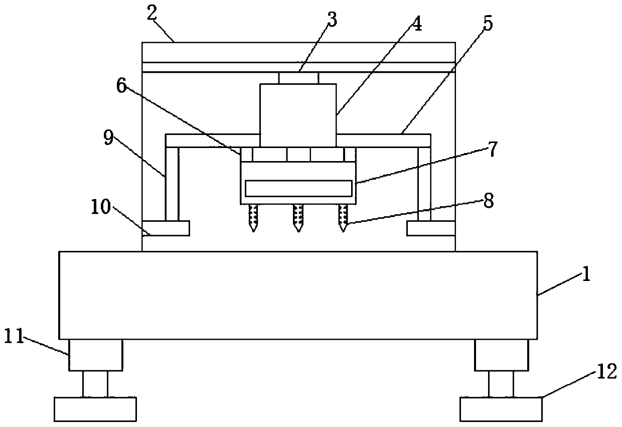
[0030] see Figure 1-5 , the present invention provides a technical solution:

[0031] A self-cleaning needling machine for textiles, comprising a base 1 and a mounting plate 2, the mounting plate 2 has an L-shaped structure, the lower end of the base 1 is fixedly connected with a shock absorbing device 11, the shock absorbing device 11 is connected with a leg 12, and the mounting plate 2. It is fixed on the upper end of the base 1 by welding. The...


PUM


Abstract

The invention discloses a self-cleaning needle machine for spinning. The self-cleaning needle machine comprises a base and a mounting plate. Damping devices are fixedly connected to the lower end of the base. Support legs are connected to the damping devices. The mounting plate is fixedly connected to the upper end of the base. Compression devices are lengthened through electric telescopic rods. Asecond compression plate compresses a to-be-processed product. A plurality of protrusion blocks can well press the to-be-processed product. A buffering effect is achieved during compression through first telescopic rods and first springs; when puncture needles lift the to-be-processed product during rising due to movement mistakes, the first telescopic rods and the first springs play a bufferingrole to prevent the to-be-processed product from being pulled to cause damage; electromagnets are started up at a certain frequency and are electrified to produce attraction forces, sliders are pushedout, steel wires are attached to the side walls of the puncture needles, and accordingly, fibers brought out by the puncture needles are cleared away to ensure good operation of the puncture needles.

Description

technical field [0001] The invention relates to the technical field of textile machinery, in particular to a self-cleaning needling machine for textile. Background technique [0002] Acupuncture machine is a blanket-forming equipment that weaves refractory fiber blankets of a certain thickness into refractory fiber blankets after compaction and acupuncture. The fiber web is repeatedly punctured by a thorn with a triangular or other shaped cross-section and with a thorn hook on the edge. The fiber web unloaded from the cross-forming or air-forming machine is very fluffy when it is fed into the needle loom. It only has a certain strength due to the cohesion between fibers, but the strength is very poor. When the needle penetrates into the fiber net, the barbed hook on the needle will drive the fibers on the surface and sub-surface of the fiber net, and move from the plane direction of the fiber net to the vertical direction of the fiber net, causing the fibers to shift up and...

Claims


Application Information

Patent Timeline
Patent Type & Authority Applications(China)
IPC IPC(8): D04H18/02B03C1/02F16F15/023F16F15/02F16F15/04
CPCB03C1/02D04H18/02F16F15/022F16F15/0232F16F15/04
Inventor 陈范生刑丽娟张莉
Owner HEFEI HUIZHI NEW MACHINERY TECH CO LTD
Why Eureka
Try Eureka