
High-gain Boost converter based on three-winding coupled inductor and working method of high-gain Boost converter

A coupled inductor and three-winding technology, applied in the field of high-gain Boost converters, can solve problems such as high voltage stress, low efficiency, and high input current ripple

Active Publication Date: 2019-09-10
HARBIN UNIV OF SCI & TECH
View PDF5 Cites 5 Cited by
  • Summary
  • Abstract
  • Description
  • Claims
  • Application Information

AI Technical Summary

Problems solved by technology

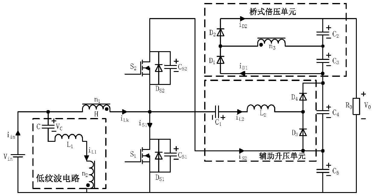
[0004] In view of the shortcomings of the prior art described above, the purpose of the present invention is to provide a working method of a high-gain Boost converter based on a three-winding coupled inductor, which is used to solve the problem of high input current ripple and voltage stress of the Boost converter in the prior art. high and low efficiency

Method used


Image

  • High-gain Boost converter based on three-winding coupled inductor and working method of high-gain Boost converter
  • High-gain Boost converter based on three-winding coupled inductor and working method of high-gain Boost converter
  • High-gain Boost converter based on three-winding coupled inductor and working method of high-gain Boost converter

Examples


Embodiment Construction

[0066] Embodiments of the present invention are described below through specific examples, and those skilled in the art can easily understand other advantages and effects of the present invention from the content disclosed in this specification. The present invention can also be implemented or applied through other different specific implementation modes, and various modifications or changes can be made to the details in this specification based on different viewpoints and applications without departing from the spirit of the present invention. It should be noted that, in the case of no conflict, the following embodiments and features in the embodiments can be combined with each other.

[0067] It should be noted that the diagrams provided in the following embodiments are only schematically illustrating the basic ideas of the present invention, and only the components related to the present invention are shown in the diagrams rather than the number, shape and number of componen...


PUM


Abstract

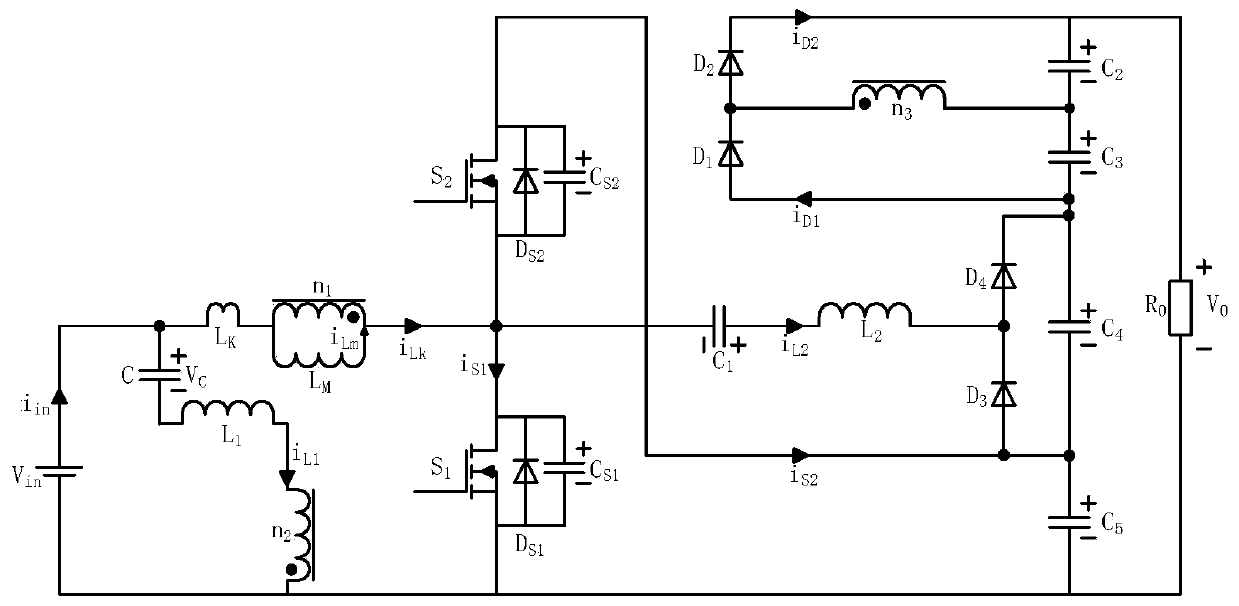
The invention provides a high-gain Boost converter based on a three-winding coupled inductor and a working method of the high-gain Boost converter. The high-gain Boost converter comprises a Boost unit, an auxiliary Boost unit, a voltage doubling unit and a low ripple unit; the Boost unit comprises a primary winding, a first switching tube, a second switching tube and a fourth capacitor and a fifthcapacitor which are connected in series; the positive electrode of a power supply is connected with the non-dotted terminal of the first winding; the dotted terminal of the primary winding is connected with the drain electrode of the first switching tube and the source electrode of the second switching tube; the source electrode of the first switching tube and the source electrode of the second switching tube are connected to the two ends of the fifth capacitor respectively; and the negative electrode of the power supply is connected with the source electrode of the first switching tube. Theproblem of low efficiency of the Boost converter in the prior art is solved.

Description

technical field [0001] The invention belongs to the field of power electronic converters, in particular to a working method of a high-gain Boost converter based on a three-winding coupled inductor. Background technique [0002] Clean energy such as solar energy and wind energy has become an important new energy source. The output voltage of photovoltaic modules generally does not exceed 50V. In order to realize the grid connection of photovoltaic energy, the output voltage of photovoltaic modules needs to be boosted to a DC bus voltage of 380-400V. Therefore, high-gain, high-efficiency DC-DC converters have attracted more and more attention from domestic and foreign researchers. [0003] The high-gain Boost converters proposed by researchers at home and abroad can be mainly divided into: 1) Cascaded Boost converters, which use the output of the front-stage converter as the input of the rear-stage converter, so that the voltage gain increases in steps, and the total The vol...

Claims


Application Information

Patent Timeline
IPC IPC(8): H02M3/158H02M1/14
CPCH02M1/14H02M3/158H02M1/0058Y02B70/10
Inventor 周美兰李晨张宇吴晓刚
Owner HARBIN UNIV OF SCI & TECH
Learn More