
A method of arc additive manufacturing of metal workpieces

A technology for additive manufacturing and metal workpieces, which is applied in the field of arc additive manufacturing, and can solve the problem of inability to build workpieces layer by layer.

Active Publication Date: 2020-10-13
南京衍构科技有限公司
View PDF9 Cites 0 Cited by
  • Summary
  • Abstract
  • Description
  • Claims
  • Application Information

AI Technical Summary

Problems solved by technology

Due to the particularity of the workpiece, there is no support under part of the path in the result of slicing, which makes it impossible to carry out layer-by-layer accumulation to realize the forming of the workpiece

Method used


Image

  • A method of arc additive manufacturing of metal workpieces
  • A method of arc additive manufacturing of metal workpieces
  • A method of arc additive manufacturing of metal workpieces

Examples


Embodiment Construction

[0022] The present invention will be described in further detail below in conjunction with specific embodiments.

[0023] Such as Figure 4 As shown, the device of the present invention includes a robot base, the robot is fixed on the robot base, and the rotating outer shaft is fixed on the positioner, and the rotating outer shaft can be rotated on a horizontal plane or turned over.

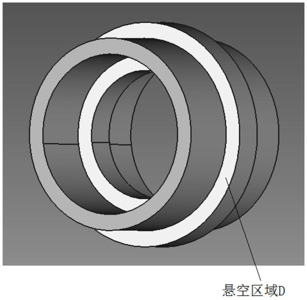
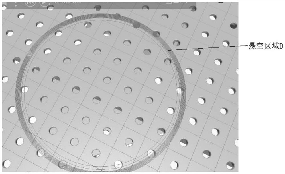
[0024] Characteristics of metal workpieces: The presence of suspended (unsupported) areas in metal workpieces such as figure 2 shown.

[0025] Such as figure 1 As shown, the arc additive manufacturing method of a metal workpiece of the present invention specifically includes the following steps:

[0026] Step 1, perform layered slices on the digital model of the parts according to the Z direction, and obtain the cross-section of each slice;

[0027] Step 2, compare the cross-sections of the upper and lower layers, find the difference between the N+1th layer and the Nth layer, and obtain the ...


PUM


Abstract

The invention discloses an electric arc additive manufacturing method for a special-structure metal workpiece, and aims at a support-free region in the metal workpiece. The method disclosed by the invention can be used for calculating the supporting point and calculating the supporting angle for each point in the supporting-free region, so that when each point is subjected to additive manufacturing, the additive manufacturing is carried out after the rotating outer shaft is turned over by a supporting angle towards a robot, and the additive manufacturing of the metal workpiece containing a suspended region is realized.

Description

technical field [0001] The invention relates to an arc additive manufacturing method for metal workpieces, belonging to the technical field of metal welding processing. Background technique [0002] Arc additive manufacturing is a manufacturing method that melts and deposits metal layer by layer to form a workpiece by welding. The traditional arc additive process usually uses slicing software to perform layered slicing and path planning on the digital model of the parts in the Z direction, and then outputs the program to the welding robot for additive operations. Due to the particularity of the workpiece, there is no support under part of the path in the result of slicing, which makes it impossible to carry out layer-by-layer accumulation to realize the forming of the workpiece. Contents of the invention [0003] Purpose of the invention: The technical problem to be solved by the present invention is to provide a method that can automatically identify the unsupported area...

Claims


Application Information

Patent Timeline
Patent Type & Authority Patents(China)
IPC IPC(8): B23K9/04B33Y10/00
CPCB23K9/044B33Y10/00
Inventor 吴玲珑刘欣迟科萌
Owner 南京衍构科技有限公司
Learn More