A metal additive manufacturing system and method

A metal additive and manufacturing system technology, applied in the direction of manufacturing tools, metal processing equipment, process efficiency improvement, etc., can solve the problems that the molten forming area cannot be cooled down quickly, the manufacturing cost is expensive, and the manufacturing efficiency is reduced, so as to achieve convenient molding , Reduce heat source power requirements, effect of size reduction

Active Publication Date: 2022-08-09
XI AN JIAOTONG UNIV
View PDF10 Cites 0 Cited by
  • Summary
  • Abstract
  • Description
  • Claims
  • Application Information

AI Technical Summary

Problems solved by technology

[0003] Additive manufacturing still has some disadvantages: material limitations, expensive manufacturing costs, low molding efficiency
The additive manufacturing of metal materials in microgravity and vacuum environment is often quite different from that in gravity environment, and the heat in vacuum environment is mainly thermal radiation, and the heat dissipation is slow, and the melting and forming area cannot be as in the air. Rapid cooling down greatly reduces manufacturing efficiency

Method used


Image

  • A metal additive manufacturing system and method
  • A metal additive manufacturing system and method
  • A metal additive manufacturing system and method

Examples


Embodiment

[0046] The workpiece support shaft is prepared by using a prefabricated mold. The device of this application is mainly used for parts such as a rotating body, and includes the following steps:

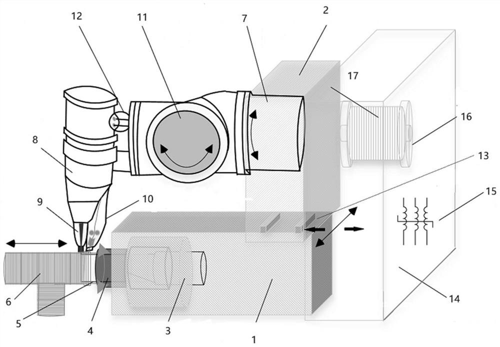
[0047] S1, according to the length and thickness of the part to be formed, set the forming displacement distance of the wire feeding forming device; according to the diameter of the inner cavity of the part to be formed, select a workpiece support shaft with an appropriate diameter;

[0048] S2, adjust the initial position of the high-energy beam and the wire feeder by the rotary manipulator to be on the surface of the workpiece support shaft forming starting point, start the forming heat source and the rotary drive motor, and the high-energy beam of the forming heat source will melt and fix the wire bundle passing through the wire feeder to the workpiece support shaft. , the control system controls the rotary manipulator to start moving, so that the high-energy beam and the wire feeder...


PUM


Abstract

The invention discloses a metal additive manufacturing system and method. A rotary support base and a wire feeding forming base are used to form a rotary forming device. By arranging a forming rotary shaft in the rotary support base, the forming rotary shaft is fixedly connected with a The workpiece support shaft that rotates synchronously with it, the wire feed forming base is connected with the forming heat source and the wire feed head through the mechanical arm, and the wire feed forming base is installed on the slewing support base through the X / Y motion platform system, and the wire feed head can The tow is laid along the surface of the workpiece support shaft, and the high-energy beam can act on the junction of the wire for fused deposition forming, which can effectively reduce the size of the melting forming area, thereby reducing the total heat of the melting forming area. Under the same conditions, the melting forming area It can be cooled and solidified quickly, and the wire winding method is adopted, which is not affected by gravity or vacuum environment, which effectively reduces the requirement of heat source power in the forming area, and also avoids the phenomenon that the tow is not tightly combined when all the tows are melted.

Description

technical field [0001] The invention belongs to a novel additive manufacturing technology, in particular to a metal additive manufacturing system and method. Background technique [0002] Additive manufacturing, commonly known as 3D printing, integrates computer-aided design, material processing and molding technology, and is based on digital model files. , melting, light curing, spraying and other methods are stacked layer by layer to create a manufacturing technology for physical objects. Compared with the traditional processing mode of raw material removal-cutting and assembly, it is a "bottom-up" manufacturing method through material accumulation, starting from scratch. According to the type of technology, there are injection molding, binder injection molding, photopolymer curing molding, material extrusion molding, laser powder sintering molding, directed energy deposition molding, etc. [0003] Additive manufacturing still has some shortcomings: material limitations,...

Claims


Application Information

Patent Timeline
Patent Type & Authority Patents(China)
IPC IPC(8): B23K26/34B23K26/342B23K26/70B23K15/00
CPCB23K26/34B23K26/342B23K26/70B23K26/702B23K15/00B23K15/0086Y02P10/25
Inventor 王磊卢秉恒汤永凯李波波张琼陈祯
Owner XI AN JIAOTONG UNIV
Why Eureka
Try Eureka