Thin-beam laser melting deposition additive manufacturing method and laser processing head used therefor

A technology of laser melting deposition and laser processing head, which is applied in the direction of additive processing, metal material coating process, coating, etc. It is suitable for high-precision parts and other problems, so as to achieve high utilization rate of laser energy, improve the quality of additive manufacturing, and avoid the effect of powder oxidation

Active Publication Date: 2021-01-19
NAT INNOVATION INST OF DEFENSE TECH PLA ACAD OF MILITARY SCI
View PDF1 Cites 0 Cited by
  • Summary
  • Abstract
  • Description
  • Claims
  • Application Information

AI Technical Summary

Problems solved by technology

The powder feeding method of the center beam usually has the following deficiencies: ①Because the powder slantly converges to the focus of the spot and then disperses again, the action range with the laser is small, and the degree of heating is different, resulting in serious powder splashing and low utilization rate; ②Due to the diameter of the powder spot It directly determines the size of the deposition spot (welding bead), and the lateral coaxial method requires high coaxiality accuracy of the laser processing head, resulting in a small adjustable range of powder spot diameter, which is difficult to reduce to below the millimeter level, which in turn leads to The deposition spot (weld bead) is wide, and the improvement of forming accuracy is limited
The current laser melting deposition additive manufacturing technology with central coaxial powder feeding mostly uses wire or metal powder as raw materials, but the width of deposited spots is mostly several millimeters or even tens of millimeters, which is not suitable for high-precision additive manufacturing of parts.

Method used


Image

  • Thin-beam laser melting deposition additive manufacturing method and laser processing head used therefor
  • Thin-beam laser melting deposition additive manufacturing method and laser processing head used therefor
  • Thin-beam laser melting deposition additive manufacturing method and laser processing head used therefor

Examples


Embodiment Construction

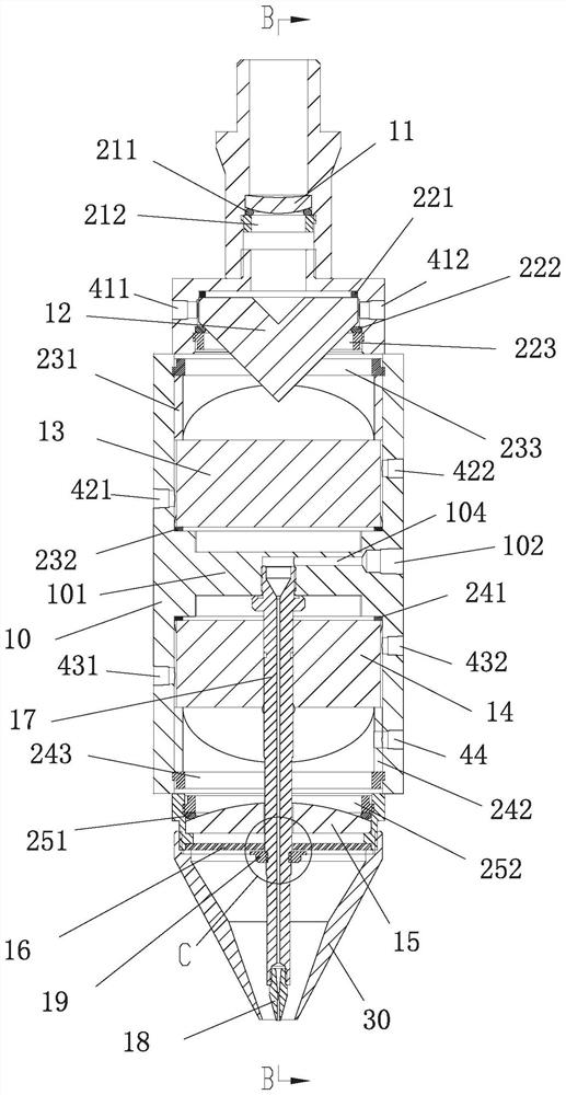
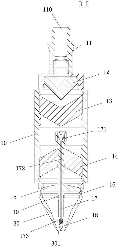
[0037] refer to Figure 10 to Figure 15 To understand, the present invention proposes a thin beam laser melting deposition additive manufacturing method, comprising the following steps:

[0038] 1) Transform an incident beam of parallel collimated laser light into an annular laser beam (such as Figure 11 );

[0039] 2) Through a pair of upper and lower refracting prisms 13 and 14 opposite to the roof ridge, the annular laser beam is first converted into two semicircular laser beams with a gap 120 between them and then restored back to the annular laser beam, wherein: Upper refraction prism 13 will circular ring laser beam (as Figure 11 ) is transformed into two semi-circular laser beams with a gap 120 between them (such as Figure 12 ), the lower refracting prism 14 restores the two semicircle ring laser beams back to the ring laser beam (as Figure 13 );

[0040] 3) by the focusing lens 15, the annular laser beam (such as Figure 13 ) converges into a fine focused spot ...


PUM

PropertyMeasurementUnit
particle sizeaaaaaaaaaa
diameteraaaaaaaaaa
Defocus amountaaaaaaaaaa

Abstract

The invention discloses a method for manufacturing thin-beam laser melting deposition addition materials and a laser machining head used in the method. The method comprises that a parallel collimatedlaser is converted into a circular annular laser beam; the circular annular laser beam is then converted into two semicircular annular laser beams with gaps and then restored back to the circular annular laser beam; the circular annular laser beam is converged to form a focusing light spot near the surface of a substrate; the powder is laterally fed from the gaps and then is accelerated to be ejected from a nozzle under the action of jet flow energy; the ejected powder meets the focused spot near the surface of the substrate; and the powder and the substrate surface are heated to fully or semi-molten states so that the powder can achieve liquid or solid phase deposition on the surface of the substrate. In practice, the ejected powder and the focusing light spot continuously move together relatively to the surface of the substrate, the powder is deposited layer by layer and thickened, and a part with a preset shape is finally formed and manufactured. According to the method, the central-coaxial powder feeding is achieved, a laser light path is not shielded, and the purpose of high-speed laser cladding or spraying with low powder splashing is achieved.

Description

technical field [0001] The invention relates to a thin-beam laser melting deposition additive manufacturing method and a laser processing head used in the manufacturing method, belonging to the technical field of laser additive manufacturing. Background technique [0002] Laser additive manufacturing (LAM) technology is a new type of manufacturing technology that uses laser as the energy source, based on the principle of layered manufacturing, and adopts the method of accumulating materials layer by layer to directly manufacture digital models into physical parts. Laser has the characteristics of high energy density, which can realize the manufacture of difficult-to-machine metals and non-metallic materials such as plastics and ceramics. At the same time, laser additive manufacturing technology also has the advantage of not being limited by the structure of parts, and can be used for complex structures, difficult processing and thin-walled materials. Manufacturing of parts. ...

Claims


Application Information

Patent Timeline
Patent Type & Authority Patents(China)
IPC IPC(8): C23C24/10B33Y10/00B33Y30/00
Inventor 王浩旭陈永雄梁秀兵胡海韵王荣胡振峰
Owner NAT INNOVATION INST OF DEFENSE TECH PLA ACAD OF MILITARY SCI
Why Eureka
Try Eureka