
Roof with ventilation layer structure and construction methodof roof

A structure and air layer technology, which is applied to the roof with a ventilation layer structure and its construction field, can solve the problems of complex building roof structure, affecting the service life of the roof, and difficult to discharge water vapor, so as to shorten the construction period and simplify the roof structure. , the effect of prolonging the service life

Inactive Publication Date: 2019-09-13
沈阳金之利科技有限公司
View PDF7 Cites 1 Cited by
  • Summary
  • Abstract
  • Description
  • Claims
  • Application Information

AI Technical Summary

Problems solved by technology

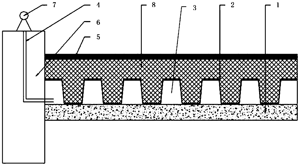
[0004] In order to solve the complex roof structure, high cost, poor moisture drainage effect, easy water leakage and the need to set a large number of exhaust windows in the existing technology, it seriously affects the service life of the roof and the defects in the floor, interior, heat preservation and slope finding materials. For technical problems such as difficult water vapor discharge, the present invention provides a roof with a ventilation layer structure and its construction method, which simplifies the roof structure, reduces the complexity of construction, improves construction efficiency, shortens the construction period, and improves Safety, with forced ventilation function, improves the quality of the roof and prolongs the service life of the roof, especially suitable for public venue buildings under high humidity conditions

Method used


Image

  • Roof with ventilation layer structure and construction methodof roof
  • Roof with ventilation layer structure and construction methodof roof

Examples


Embodiment Construction

[0029] The following will clearly and completely describe the technical solutions in the embodiments of the present invention with reference to the accompanying drawings in the embodiments of the present invention. Obviously, the described embodiments are only some of the embodiments of the present invention, not all of them. In the description of the present invention, it should be noted that the terms "upper", "lower", "inner", "outer", "front end", "rear end", "both ends", "one end", "another end" The orientation or positional relationship indicated by etc. is based on the orientation or positional relationship shown in the drawings, and is only for the convenience of describing the present invention and simplifying the description, rather than indicating or implying that the referred device or element must have a specific orientation, use a specific Azimuth configuration and operation, therefore, should not be construed as limiting the invention. In addition, the terms "fi...


PUM


Abstract

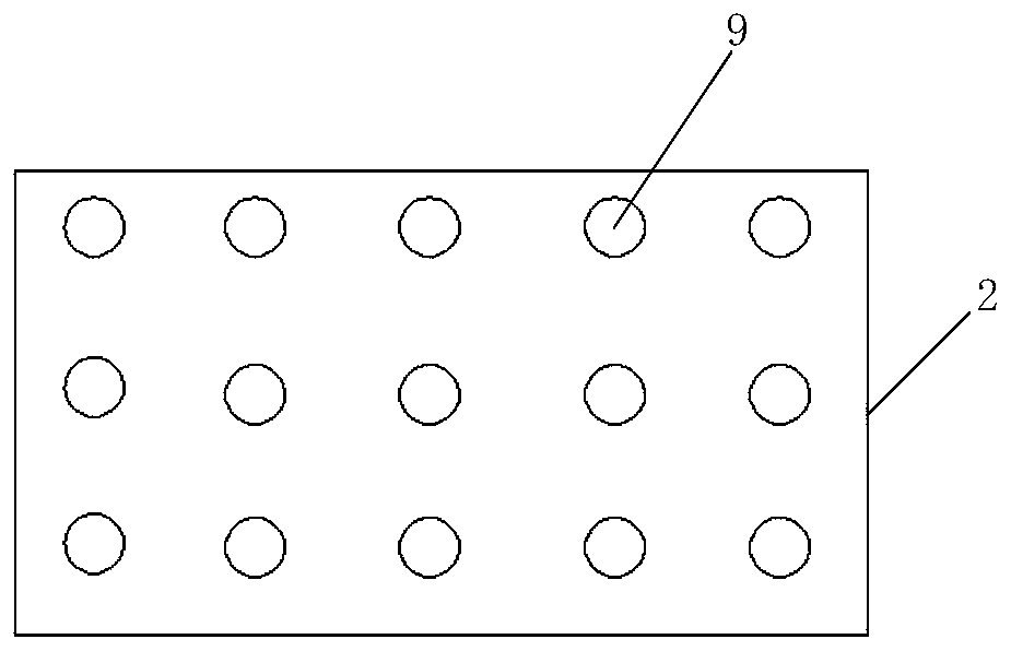
The invention discloses a roof with a ventilation layer structure and a construction method of the roof, andbelongs to thetechnical field of building roof structure design and roof heat insulation andwaterproof. The roof with the ventilation layer structure comprises a unidirectional moisture-removing supporting plate and a protective layer which are arranged in sequence above aroof floor slab, the unidirectionalmoisture-removing supporting plate is made of a polymer material, and a plurality of column feet are arranged on the side, close to the roof floor slab, of the unidirectionalmoisture-removing supporting plate. The column feet are in contact with the roof floor slab, so that a moisture-removingspace is formed between the unidirectional moisture-removingsupporting plate and the rooffloor slab, the moisture-removingspace is connected to the outside through at least one moisture-removingpipe, one end of the moisture-removingpipe is arranged in the moisture-removingspace, the other end of themoisture-removingpipe is connected with an induced draft fan, and the unidirectional moisture-removingsupporting plate is poured with a compression resistance high strength slurry. According to the roof with the ventilation layer structure and the construction method of the roof,the roof structure issimplified, the complexity of the construction isreduced, the construction work efficiency isimproved, the safety isimproved, a forced ventilation function is achieved, the quality of the roof isimproved, the roof service life isprolonged, and the roofand the construction method areespecially suitable for public venue buildings in high humidity condition.

Description

technical field [0001] The invention relates to the technical field of building roof structure design and roof insulation and waterproofing, in particular to a roof with a ventilation layer structure and a construction method thereof. Background technique [0002] At present, the construction method of building roof is mainly composed of floor slab, mortar leveling layer, vapor barrier layer, slope layer, thermal insulation layer, flexible material waterproof layer and rigid mortar protective layer. Among them, moisture drainage and exhaust pipe structures are arranged in the middle above the vapor barrier layer and below the waterproof layer to discharge the moisture in the insulation layer and prevent the roof from swelling, bulging, cracking and damage when the temperature is high in summer and condensation when it is cold in winter , frost heave and freeze-thaw damage. [0003] However, because there are a large number of pores and seams in the materials in the slope-fi...

Claims


Application Information

Patent Timeline
Patent Type & Authority Applications(China)
IPC IPC(8): E04D13/17E04D13/00E04D11/02E04D3/24E04D13/16E04F17/04
CPCE04D3/24E04D11/02E04D13/00E04D13/16E04D13/172E04F17/04
Inventor 陈星唐小卫江云林鲁永明
Owner 沈阳金之利科技有限公司
Learn More