
Path detection platform

A path detection and platform technology, applied in the direction of measuring devices, vehicle testing, mechanical component testing, etc., can solve the problems of small number of mules, tight vehicles, low efficiency, etc., saving labor, sufficient time, and platform structure. simple effect

Inactive Publication Date: 2019-09-13
NIO ANHUI HLDG CO LTD
View PDF5 Cites 0 Cited by
  • Summary
  • Abstract
  • Description
  • Claims
  • Application Information

AI Technical Summary

Problems solved by technology

[0003] Traditional path detection needs to be completed on the whole vehicle, but there are at least the following problems: 1. The path detection requires a real vehicle, but the number of mule vehicles is small in the early stage of vehicle development, and various pre-function development projects lead to a shortage of vehicles; 2. In the path After the initial detection is completed, it is usually necessary to optimize the path, such as adjusting fixed points, modifying peripheral parts, and adjusting path length, and it needs to be verified again on the improved real vehicle, and the improvement process is due to fixed points, peripheral parts, and path length. According to the verification process, it often takes 3 to 5 rounds to confirm the final path, and this process takes a long time, high cost, slow progress, and low efficiency

Method used


Image

  • Path detection platform
  • Path detection platform
  • Path detection platform

Examples


Embodiment 1

[0074] Embodiment 1. Front Angle Assembly Path Detection Platform

[0075] Such as Figure 6 The platform shown is used to test the front corner assembly with air suspension structure. Due to the symmetry of the vehicle, only 1 / 2 of the front corner assembly needs to be installed on the platform, that is, 1 / 4 of the corner assembly . The assembly points where the front corner assembly needs to be fixed on the body include: air suspension body fixing points, upper control arm body fixing points, front lower front control arm subframe fixing points, front lower rear control arm subframe fixing points, The path is at a fixed point of the vehicle body, and the path includes one or more of a wheel speed path, a hose path, a friction alarm path, and the like. The connection structures 2 corresponding to the above-mentioned assembly points on the frame structure 1 are: the first air suspension connection structure 21, the first upper control arm connection structure 22, the front l...

Embodiment 2

[0077] Embodiment 2: Back Angle Assembly Path Detection Platform

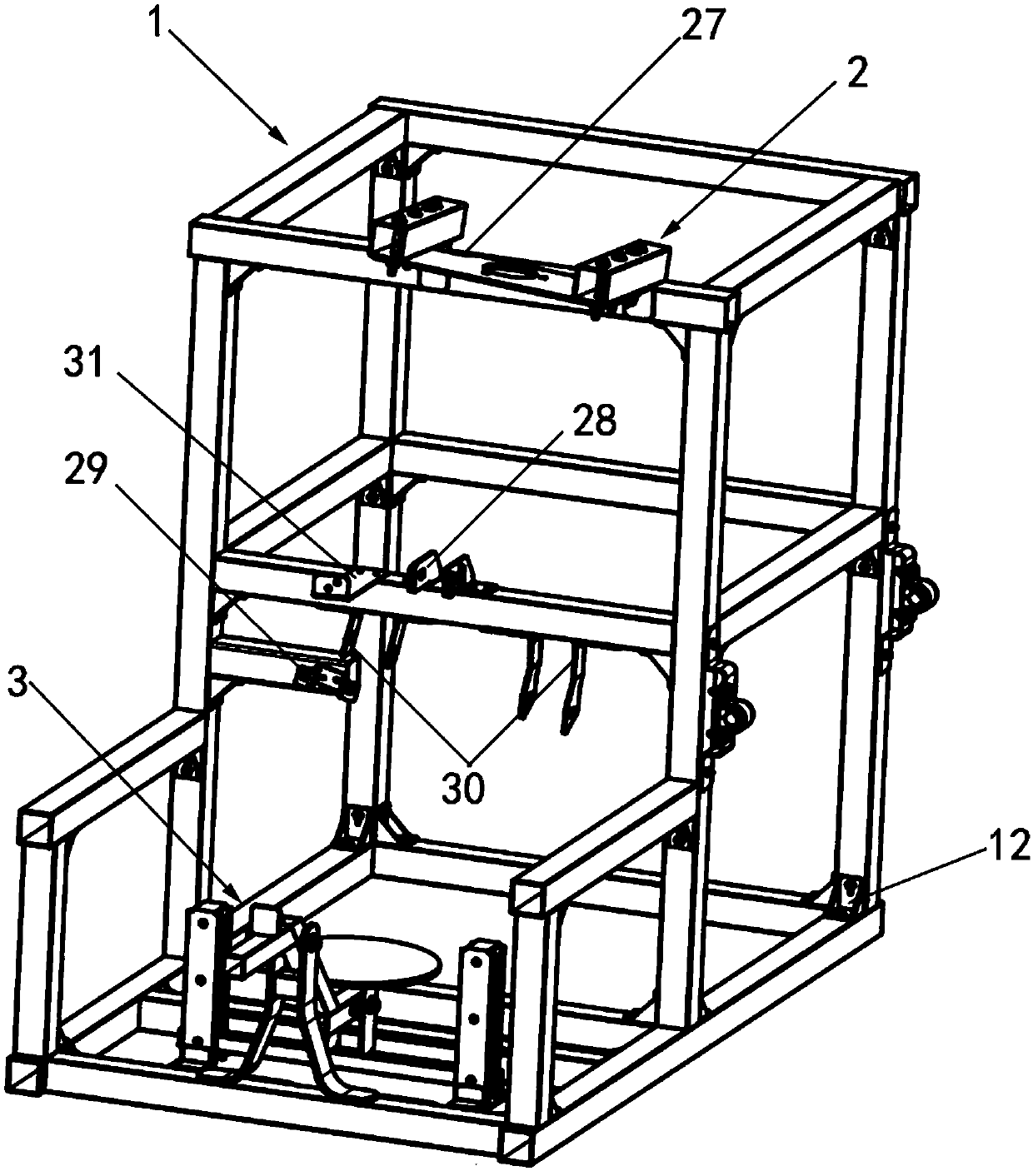
[0078] Such as figure 1 The platform shown is used to test the rear corner assembly with an air suspension structure. Due to the symmetry of the vehicle, only 1 / 2 of the front and rear assemblies need to be installed on the platform, that is, 1 / 4 of the corner assembly. The assembly points where the rear corner assembly needs to be fixed on the body include: air suspension body fixing points, upper control arm body fixing points, H-arm sub-frame fixing points, trailing arm sub-frame fixing points, path fixing on the body point; the path includes one or more of a wheel speed path, a hose path, a friction alarm path, and the like. The connection structures 2 corresponding to the above assembly points on the frame structure 1 are: the second air suspension connection structure 27, the second upper control arm connection structure 28, the H arm connection structure 29, the trailing arm connection structure 30, the...


PUM


Abstract

The invention relates to a path detection platform. The path detection platform comprises a frame structure and multiple connection structures arranged on the frame structure, wherein the connection structures are used for connecting assembly points to be fixed on a vehicle body on a tested corner assembly, the tested corner assembly is fixed on the frame structure. In path detection, a whole vehicle is not needed, the tested corner assembly only needs to be installed on the path detection platform; and path optimization can be completed before installation of the whole vehicle, so that time for path detection and path optimization is shortened greatly, and the efficiency is improved.

Description

technical field [0001] The invention relates to the technical field of vehicle path detection, in particular to a path detection platform. Background technique [0002] During vehicle design and development, it is necessary to test and verify the entire vehicle, its important components, and route layout. The path of the vehicle refers to the circuit formed by the parts fixed on the body connected by cables, for example, the wheel speed path, including wheel speed sensors, cables, wire buckles, rubber sleeves and connectors, etc. Speed ​​information is sent to the vehicle controller. Whether the path layout is reasonable under static and dynamic conditions: for example, whether the gap between the path and the vehicle components around the path (referred to as peripheral parts) is reasonable, that is, whether there will be interference; whether the fixed point position of the path is reasonable, whether the fixed point of the path is reasonable Durability; whether the path...

Claims


Application Information

Patent Timeline
Patent Type & Authority Applications(China)
IPC IPC(8): G01M17/007G01M13/00
CPCG01M13/00G01M17/007
Inventor 陶乐晓
Owner NIO ANHUI HLDG CO LTD
Learn More