
Galvanometer welding system adopting coaxial visual positioning function

A visual positioning and welding system technology, applied in welding equipment, laser welding equipment, metal processing equipment, etc., can solve the problem that it is difficult to adjust the distance between the 45° light-transmitting mirror seat and the welding component of the camera, and the galvanometer welding system is difficult to achieve multi-point welding and other problems, to achieve the effect of improving production efficiency and flexibility, reliable welding, and simple software operation

Inactive Publication Date: 2019-09-17
SHENZHEN TONGFA LASER EQUIP
View PDF8 Cites 1 Cited by
  • Summary
  • Abstract
  • Description
  • Claims
  • Application Information

AI Technical Summary

Problems solved by technology

[0004] The purpose of the present invention is to provide a galvanometer welding system using coaxial visual positioning to solve the problem that the galvanometer welding system is difficult to achieve fast and accurate multi-point welding and the galvanometer welding system is difficult to adjust 45° when using the existing galvanometer welding system The distance between the light-transmitting lens seat and the camera and the welding component

Method used


Image

  • Galvanometer welding system adopting coaxial visual positioning function
  • Galvanometer welding system adopting coaxial visual positioning function
  • Galvanometer welding system adopting coaxial visual positioning function

Examples


Embodiment Construction

[0023] The following will clearly and completely describe the technical solutions in the embodiments of the present invention with reference to the accompanying drawings in the embodiments of the present invention. Obviously, the described embodiments are only some, not all, embodiments of the present invention. Based on the embodiments of the present invention, all other embodiments obtained by persons of ordinary skill in the art without making creative efforts belong to the protection scope of the present invention.

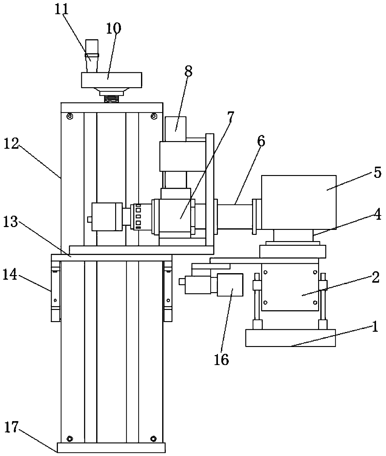
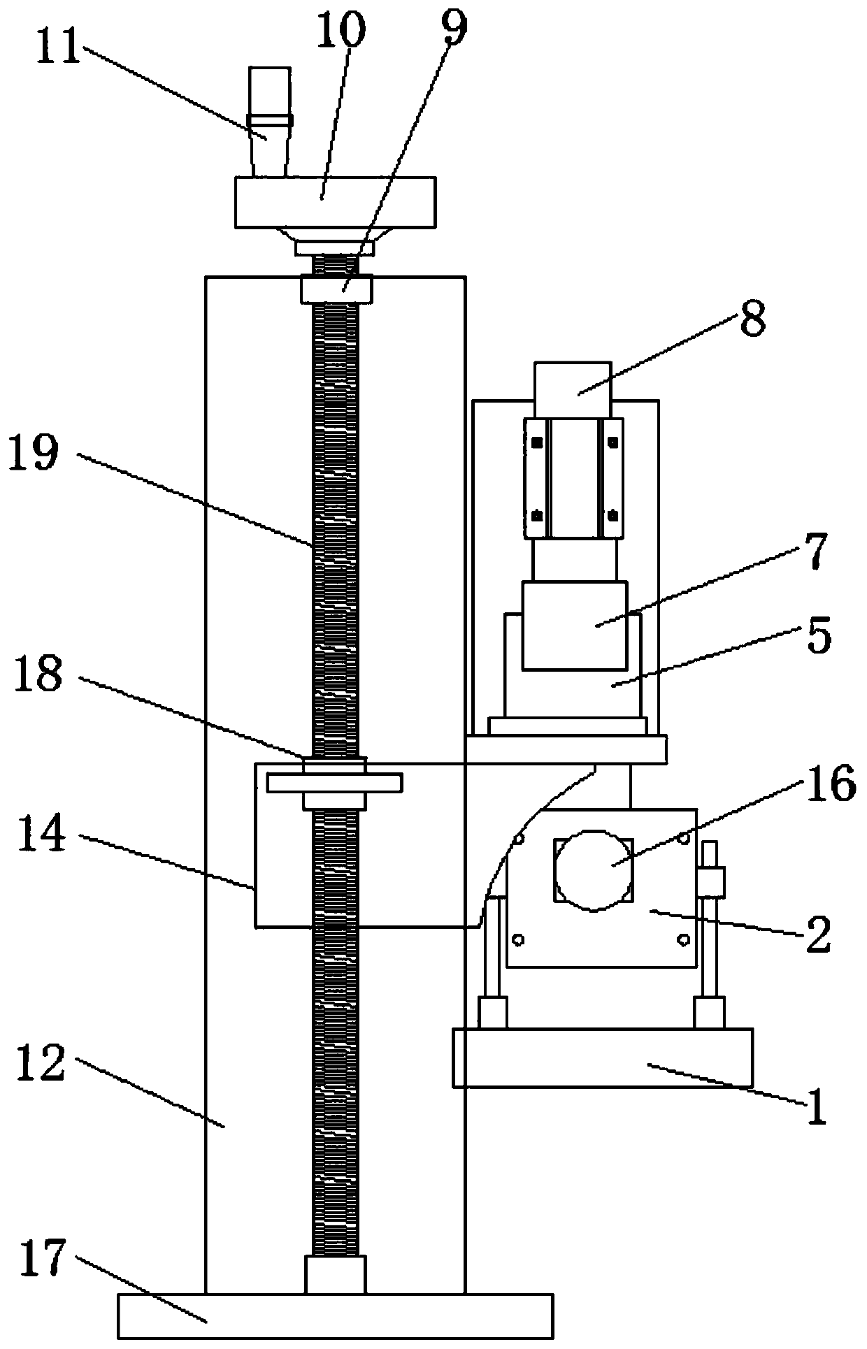
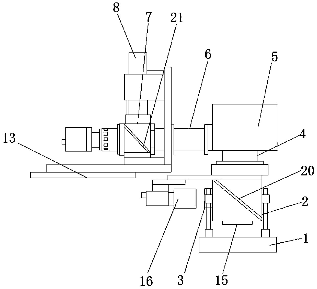
[0024] see Figure 1-4 As shown, the present invention provides the following technical solutions: a galvanometer welding system using coaxial visual positioning, including a 45° reflector base 7, is characterized in that: the top of the 45° reflector base 7 is connected to an optical fiber laser inlet through an airtight connection pipeline Terminal 8, one side of the 45° reflector seat 7 is connected with a sealed transmission optical channel 6, the end of t...


PUM

PropertyMeasurementUnit
diameteraaaaaaaaaa

Abstract

The invention discloses a galvanometer welding system adopting a coaxial visual positioning function. The galvanometer welding system involves a 45-degree reflector base, the top end of the 45-degree reflector base is connected with an optical fiber laser inlet end through a closed connecting pipeline, one side of the 45-degree reflector base is connected with a closed transmission light channel, the tail end of the closed transmission light channel is connected with a scanning galvanometer, an output end of the bottom of the scanning galvanometer is connected to a 45-degree light-transmitting lens base through a galvanometer transmission light channel, a reflecting light outlet end is arranged on one side of the 45-degree light-transmitting lens base, the bottom end of the 45-degree light-transmitting lens base is provided with a transmission light outlet end, a frame type light supplementing lamp is arranged at the bottom end of the 45-degree light-transmitting lens base, and an industrial camera is arranged on one side of the 45-degree light-transmitting lens base. The system has very strong time advantages on array type and intensive welding spot processing. Compared with traditional welding, the galvanometer welding system adopting vision capturing is matched with professional graphic processing software, and thus instant multi-point welding based on program control is realized.

Description

technical field [0001] The invention belongs to the technical field of vibrating mirror welding, and in particular relates to a vibrating mirror welding system adopting coaxial vision positioning. Background technique [0002] Laser welding is to radiate a laser beam with high energy density to the metal surface. Under the interaction between the laser and the metal, the metal absorbs the laser energy and converts it into heat energy. After the metal melts, it cools and crystallizes to form a weld. Lithium battery laser welding system is mainly composed of fiber laser, laser welding head, automatic focus adjustment system, visual positioning system, five-axis linkage workbench, CCD monitoring system and purification and ventilation system. Compared with traditional welding methods, laser welding has the following advantages: 1. Laser beam focus diameter is less than 0.5mm, power density is higher than 105-107W / cm2, heat-affected zone is small, workpiece deformation after wel...

Claims


Application Information

Patent Timeline
Patent Type & Authority Applications(China)
IPC IPC(8): B23K26/21B23K26/064
CPCB23K26/0643B23K26/0648B23K26/21
Inventor 王小峰
Owner SHENZHEN TONGFA LASER EQUIP
Learn More