
Shore bridge tilting-snagging integrated electric hydraulic control system and method

An electro-hydraulic control system and electro-hydraulic control technology, which are used in the testing of fluid pressure actuation systems, load suspension components, fluid pressure actuation devices, etc., can solve high energy consumption, complex hydraulic pipelines, and complex fault handling problems, to achieve the effect of reducing the number of spare parts, reducing the amount of construction, and reducing repeated designs

Pending Publication Date: 2019-09-17
SHANGHAI ZHENHUA HEAVY IND
View PDF10 Cites 1 Cited by
  • Summary
  • Abstract
  • Description
  • Claims
  • Application Information

AI Technical Summary

Problems solved by technology

[0004] In view of the above-mentioned defects existing in the prior art, the purpose of the present invention is to provide an integrated electro-hydraulic control system and control method for the tilting of the quay crane and the storage tank, and to change the system configuration of the existing system, and to provide a centralized hydraulic station for the The oil proportional valve controls the hydraulic cylinder system, which is changed to a distributed and integrated servo direct drive pump to control the hydraulic cylinder system, which improves the existing system's shortcomings of complex hydraulic pipelines, high energy consumption, and complex fault handling

Method used


Image

  • Shore bridge tilting-snagging integrated electric hydraulic control system and method
  • Shore bridge tilting-snagging integrated electric hydraulic control system and method

Examples


Embodiment Construction

[0025] The technical solutions of the present invention will be further described below in conjunction with the accompanying drawings and embodiments.

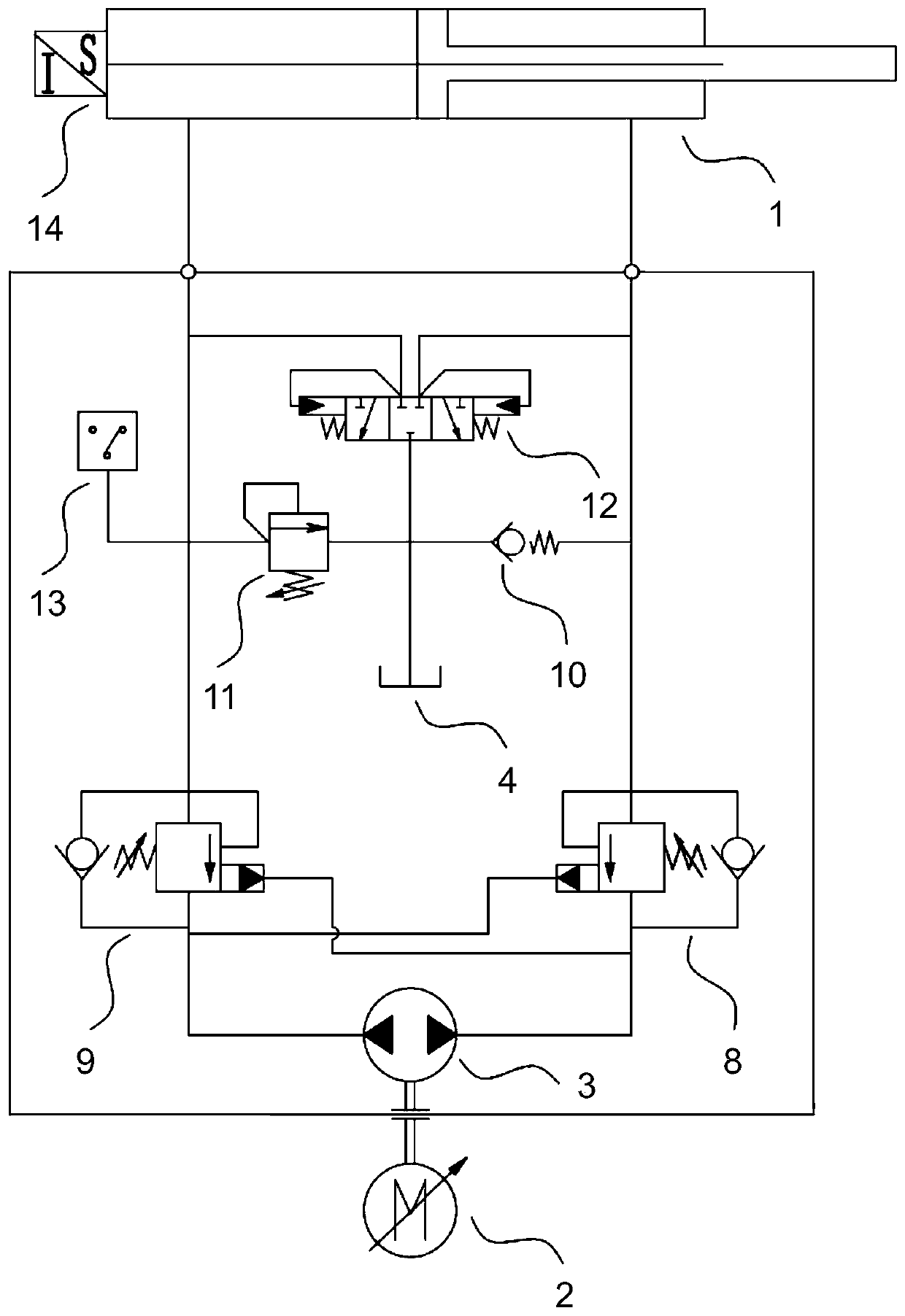
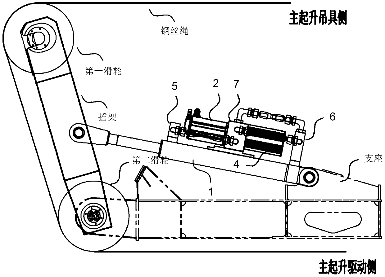
[0026] Please combine Figure 1 to Figure 2 As shown, an integrated electro-hydraulic control system for quay crane tilting and storage tank provided by the present invention includes a servo driver, an electro-hydraulic drive module and a hydraulic cylinder 1 connected in sequence.

[0027] Preferably, the electro-hydraulic drive module includes a servo motor 2, a hydraulic pump 3, a valve block 7 and an integrated oil tank 4, the servo motor 2 is electrically connected to the servo driver, and one end surface of the valve block 7 is connected to the servo motor The other end of the valve block 7 is connected and sealed with the mounting flange of the integrated oil tank 4. The hydraulic pump 3 is placed in the integrated oil tank 4. The input shaft of the hydraulic pump 3 is connected to the servo motor 2 through a coupling....


PUM


Abstract

The invention provides a shore bridge tilting-snagging integrated electric hydraulic control system and method. The system comprises a servo driver, an electric hydraulic drive module and a hydraulic cylinder; the electric hydraulic drive module comprises a servo motor, a hydraulic pump, a valve block and an integration oil tank, the servo motor is connected with the servo driver, one end face of the valve block is connected with the face, with a flange, of the servo motor, the other end face of the valve block and the face, with a flange, of the integration oil tank are connected and sealed, the hydraulic pump is arranged inside the integration oil tank, an input shaft of the hydraulic pump is connected with an output shaft of the servo motor through a coupler, and an oil port of the hydraulic pump is connected with the valve block through a hydraulic pipe; input / output hydraulic oil of the hydraulic pump passes through the valve block and then the hydraulic pump is separately connected with a first oil way block and a second oil way block by adopting hydraulic pipes, and the first oil way block and the second oil way block control the hydraulic cylinder. By changing the configuration of an existing system into a distributed integrated servo direct drive pump control hydraulic cylinder system, the defects that an existing system hydraulic pipelines is complex, energy dissipation is high, and fault handling is complex are overcome.

Description

technical field [0001] The invention relates to the field of port machinery quay cranes, and more specifically, relates to an electro-hydraulic control system and a control method for the quay crane tilting-storage integration. Background technique [0002] The quay crane in the container terminal is the core equipment in the loading and unloading system. The operating state of the equipment must be in a highly controllable state. Once an uncontrollable state occurs, it is very easy to cause the safety of the quay crane or even the loading and unloading ship. The tilting-storage system of the quay crane is a system to improve the operation efficiency and deal with the risk of hanging the warehouse urgently. Since both the tilting function and the hanging warehouse function are controlled by controlling the state of the main hoisting wire rope, the above two functions are combined Integrate in a unified system. [0003] The tilting-storage system is an essential system for t...

Claims


Application Information

Patent Timeline
Patent Type & Authority Applications(China)
IPC IPC(8): B66C13/20F15B11/00F15B19/00
CPCB66C13/20F15B11/00F15B19/00
Inventor 胡中望宋豫刘冬一张建敏
Owner SHANGHAI ZHENHUA HEAVY IND
Learn More