
A pipeline generator and its electric valve

An electric valve and generator technology, applied in the directions of hydropower, engine components, impact engines, etc., can solve problems such as failure to meet usage standards, inability to generate power smoothly, and fluid pressure reduction, and achieve cost savings and high energy utilization efficiency. , the effect of speeding up the impeller speed

Active Publication Date: 2020-05-22
秦皇岛凡尔科技有限公司
View PDF9 Cites 1 Cited by
  • Summary
  • Abstract
  • Description
  • Claims
  • Application Information

AI Technical Summary

Problems solved by technology

The pipeline generator in the present invention is connected with other pipelines through the connecting end provided on the body, and uses the flow and pressure of the fluid in the pipeline to push the impeller to rotate, drive the rotor to rotate, and interact with the stator to generate current. The above pipeline generator There are the following disadvantages: (1) Since the pipeline generator is built in the pipeline, when fluid passes through, it will absorb the kinetic energy of the fluid to a certain extent and convert it into electrical energy. When the fluid flow in the pipeline is large, the fluid in the pipeline will The pressure difference between the front and back of the pipeline generator will be very large, and the pressure at the back end of the pipeline generator will be significantly lower than the pressure at the front end. When multiple pipeline generators of the present invention are used on the entire pipeline system, the fluid pressure in the equipment at the pipeline terminal will The reduction is much lower, and some will not meet the use standard (2) At the same time, the pipeline generator is built in the pipeline, and the fluid in the pipeline directly drives the impeller to drive the rotor to rotate, and interacts with the stator to generate current. When the fluid flow rate in the pipeline is large, the power generation is fast. The power generation is slow when the fluid flow rate is small, and the power generation cannot be stable
[0005] The valve is an important component to realize the switch control of the fluid pipeline. It is widely used in the fluid pipeline at present, but there are few electric valves that cooperate with the pipeline generator.

Method used


Image

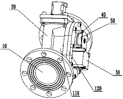
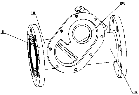
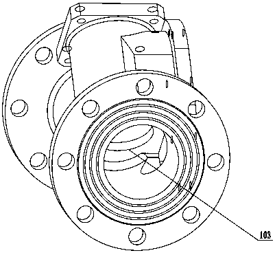
  • A pipeline generator and its electric valve
  • A pipeline generator and its electric valve
  • A pipeline generator and its electric valve

Examples


Embodiment Construction

[0051] In order to make the above objects, features and advantages of the present invention more comprehensible, specific implementations of the present invention will be described in detail below in conjunction with the accompanying drawings. In the following description, numerous specific details are set forth in order to provide a thorough understanding of the present invention. However, the present invention can be implemented in many other ways different from those described here, and those skilled in the art can make similar improvements without departing from the connotation of the present invention, so the present invention is not limited by the specific implementations disclosed below.

[0052] It should be noted that when an element is referred to as being “disposed on” another element, it may be directly on the other element or there may also be an intervening element. When an element is referred to as being "connected to" another element, it can be directly connect...


PUM


Abstract

The invention provides a motorized valve. The motorized valve comprises a valve body, a regulating seat, a stepping motor, a lead screw and a valve core, wherein the regulating seat is arranged on the upper end face of the valve body, the stepping motor is arranged on the upper end face of the regulating seat, the lead screw is located in the regulating seat, the upper end of the lead screw is connected with a motor shaft of the stepping motor, the upper end of the valve core is connected with the rear end of the lead screw, a square section slide hole is formed in the regulating seat, a slide block is arranged at the upper end of the valve core, and the slide block is connected with the lead screw in threaded mode, and installed in the square section slide hole in sliding mode. By changing opening degree of the motorized valve, pressure and flow of liquid at a body inlet end or outlet end can be changed, stable running of a fluid power device is facilitated, and electric generation is smooth and steady. The invention simultaneously provides a pipeline electric generator using the motorized valve.

Description

technical field [0001] The invention relates to the technical field of pipeline generators, in particular to a pipeline generator and an electric valve thereof. Background technique [0002] Electricity is an important energy source. People’s production and life are inseparable from electricity. A generator is a mechanical device that converts other forms of energy into electrical energy. There are many types of generators, but their working principles are based on the law of electromagnetic induction. and the laws of electromagnetism. [0003] At present, oil transmission pipelines and natural gas transmission pipelines usually require electronic instruments to test parameters such as pipeline fluid flow, pressure and temperature. Because pipelines are often located in remote locations without electrical power, meters are often wired or battery powered. But the battery has a certain life cycle, so it needs to be replaced with a new battery every once in a while. Cables n...

Claims


Application Information

Patent Timeline
Patent Type & Authority Patents(China)
IPC IPC(8): F03B11/00F03B13/00F03B1/04F03B15/20
CPCF03B1/04F03B11/004F03B13/00F03B15/20Y02E10/20
Inventor 朱淑娟贺永轩丁长远乔伟立白玉王众
Owner 秦皇岛凡尔科技有限公司
Learn More