
Two-dimensional calculation method for composite material layer cracking

A composite material layer and calculation method technology, applied in the field of two-dimensional calculation of composite material spallation, can solve problems such as troublesome grid division, achieve the effects of low grid size requirements, avoid repeated iterations, and improve calculation efficiency

Active Publication Date: 2019-09-17
HEFEI GENERAL MACHINERY RES INST +1
View PDF2 Cites 4 Cited by
  • Summary
  • Abstract
  • Description
  • Claims
  • Application Information

AI Technical Summary

Problems solved by technology

The cohesive force element is the most widely used method, but the high requirements of the mesh size of the cohesive element method limit its application in large-scale composite material structures; although the virtual crack closure technology has low requirements for the mesh size, it requires the element boundary and layer The crack propagation path coincides, which brings great trouble to mesh division; in the extended finite element, although the element boundary does not need to coincide with the spall propagation path, it needs to be used in combination with the spall propagation criterion

Method used


Image

  • Two-dimensional calculation method for composite material layer cracking
  • Two-dimensional calculation method for composite material layer cracking
  • Two-dimensional calculation method for composite material layer cracking

Examples


Embodiment Construction

[0058] The embodiment adopted by the present invention is a double cantilever beam model, and the geometric dimensions are as follows: Figure 4 As shown, the left end of the model is fixed, and a pair of balance forces of equal magnitude and opposite directions are applied to the upper and lower vertices of the right end, and the magnitude is P. The model includes two layers of composite materials and an intermediate layer. The intermediate layer is the layer where spallation occurs. Layer prefabricated 30mm long layer cracks, according to Figure 8 As shown, it can be judged that the crack is a type I crack. The material constant of the composite layer is: Young's modulus E in the fiber direction 11 =150GPa, transverse Young's modulus E 22 =11GPa, shear modulus G 12 =60GPa, Poisson's ratio υ 12 = 0.21. The middle layer is isotropic material, its Young's modulus is E=10GPa, Poisson's ratio υ=0.3, fracture toughness G IC =0.026Nmm -1 .

[0059] This embodiment adopts t...


PUM


Abstract

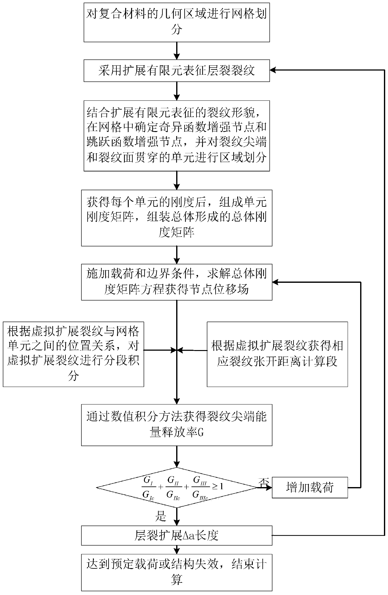
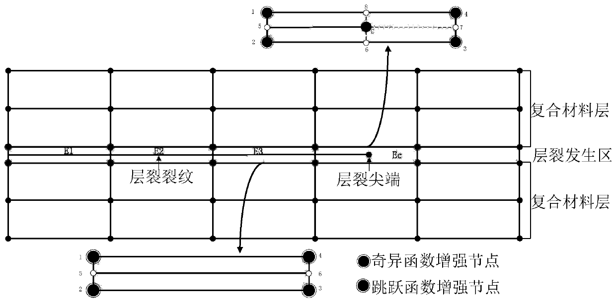
The invention discloses a two-dimensional calculation method for composite material layer cracking. The method comprises the following steps: S1, solving node displacement by adopting an extended finite element method; S2, based on the virtual crack closing technology, the energy release rate of the tip of the layer crack is obtained; S3, judging whether the layer cracks are expanded or not; and S4, when a predetermined load is reached or the structure fails, ending the calculation. The method has the advantages that the virtual crack closing technology and the expansion finite element method are combined, the expansion finite element is adopted for representing the layer crack, the unit boundary does not need to be matched with the crack shape when the grid is divided, and the grid does not need to be divided again when layer crack expansion is simulated; the requirement of layer cracking simulation on the unit size is reduced, and the calculation result is more accurate than that of a cohesion unit method; and when layer splitting expansion analysis is carried out, iteration is not needed, and the calculation efficiency is improved.

Description

technical field [0001] The invention relates to the field of damage simulation of composite materials, in particular to a two-dimensional calculation method for spallation of composite materials. Background technique [0002] Due to the advantages of high specific modulus, high specific strength, and easy design of performance, composite materials are more and more widely used in aerospace, automotive, sporting goods, pressure vessels and other fields. However, multiple damage modes have been found in composite materials during use, including fiber breakage, matrix cracking, and lamination. Theory and engineering experience show that spallation is the most common damage mode of composite materials, and the occurrence of spallation will seriously reduce the structural strength, stiffness and integrity of composite materials. Therefore, the numerical analysis of spallation is of great significance to the structural design and strength analysis of composite materials. [0003...

Claims


Application Information

Patent Timeline
Patent Type & Authority Applications(China)
IPC IPC(8): G06F17/50
CPCG06F30/23G06F30/20Y02T90/00
Inventor 江勇范志超陈学东吴乔国
Owner HEFEI GENERAL MACHINERY RES INST
Learn More