Motor rotor punching plate for deep groove type three-groove continuous structure

A motor rotor, deep groove technology, applied in the magnetic circuit shape/style/structure, asynchronous induction motor, electric components, etc., can solve the impact of material utilization and motor power density, adverse effects of motor noise, easy to generate burrs, etc. problems, to achieve the effect of improving material utilization, reducing rotor copper consumption, and reducing burrs

Pending Publication Date: 2019-09-17
WOLONG ELECTRIC GRP CO LTD
View PDF0 Cites 0 Cited by
  • Summary
  • Abstract
  • Description
  • Claims
  • Application Information

AI Technical Summary

Problems solved by technology

[0002] At present, the rotor punches used in three-phase asynchronous motors are mostly single-slot open slot structures. In actual processing, the slot shape of the open slot rotor is prone to burrs, which will have a negative impact on the noise of the motor; for some special working conditions If the motor has high efficiency under the rated state and excellent starting performance during the starting process, the traditional convex groove design of the rotor can control the starting current and increase the starting torque, but it will cause magnetic density The distribution of the upper part of the rotor teeth is too sparse and the lower part is saturated, which affects the material utilization rate and the power density of the motor.

Method used


Image

  • Motor rotor punching plate for deep groove type three-groove continuous structure
  • Motor rotor punching plate for deep groove type three-groove continuous structure
  • Motor rotor punching plate for deep groove type three-groove continuous structure

Examples


Embodiment Construction

[0017] The technical solution of the present invention will be further described in detail below in conjunction with the accompanying drawings.

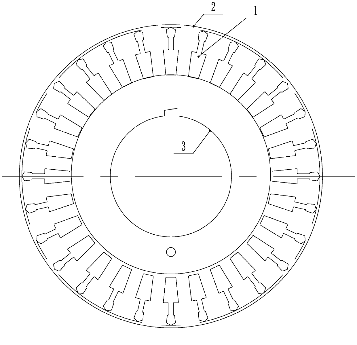
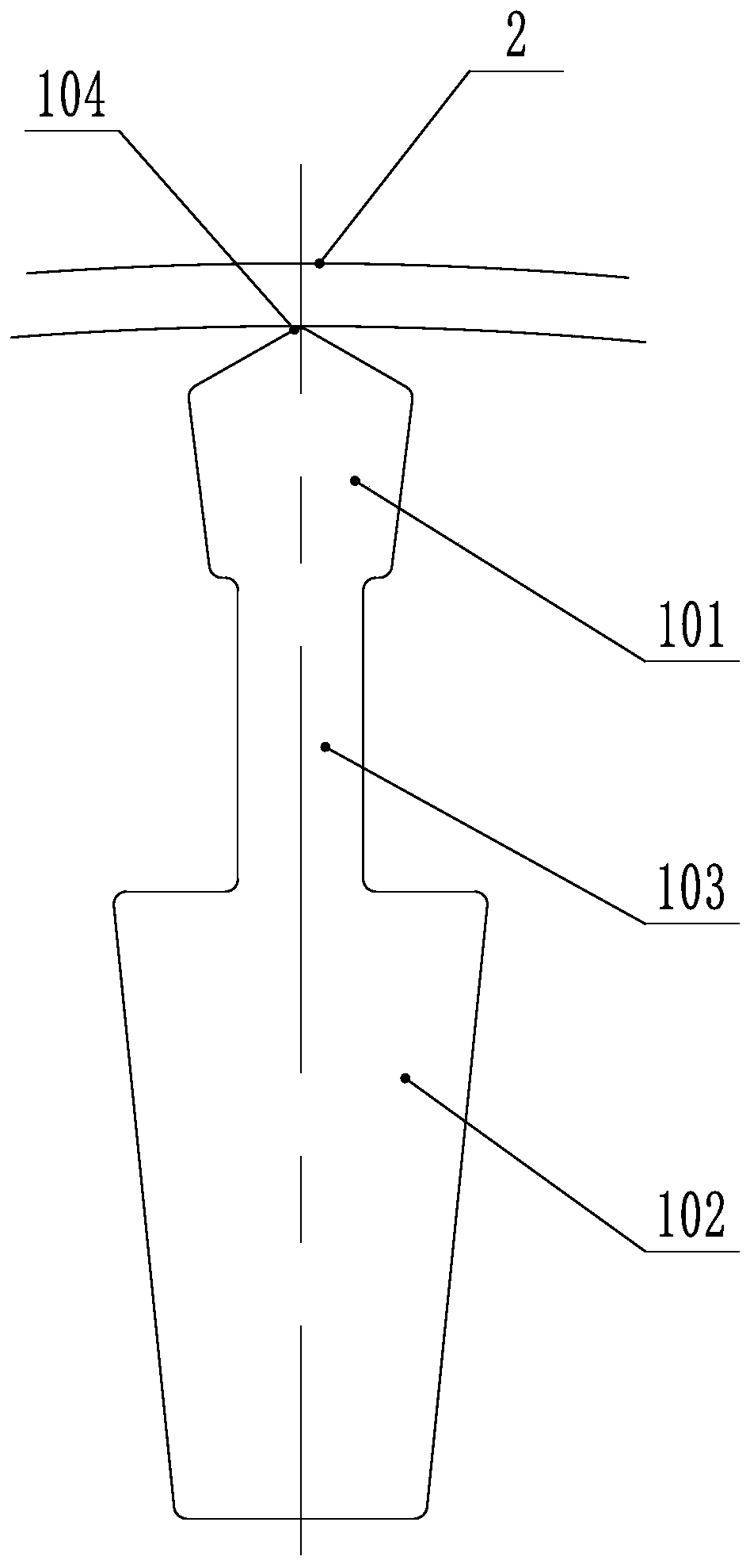
[0018] Such as Figure 1-2 As shown, a motor rotor punching sheet with a deep-groove three-slot continuous structure has punching grooves 1 evenly distributed around the rotor punching sheet. The punching grooves 1 are symmetrical according to their radial centerlines. The slender shape of the groove-type three-groove continuous structure, including the first groove part 101 located on the radially outer side, the second groove part 102 located on the radially inner side, and the first groove part 101 and the second groove part 102 pass through the bottleneck in the middle The connecting grooves 103 in the shape of the first groove are connected, the first groove 101 is a polygonal structure, the connecting groove 103 is a rectangular structure, the cross-sectional area of ​​the second groove 102 is larger than that of the first groo...


PUM


Abstract

The invention discloses a motor rotor punching plate for a deep groove type three-groove continuous structure and relates to the field of a motor. A three-phase asynchronous motor rotor punching plate is mostly a single-groove open groove structure, is easy to have burrs during processing, the groove shape may cause uneven magnetic density distribution, which affects the material utilization rate and motor power density. A punching plate groove is the elongated closed groove shape of a deep groove type continuous structure and includes a first groove portion, a connecting groove portion and a second groove portion which are continuously communicated from a radial outer side to a radial inner side of the punching plate, the first groove portion is a polygonal structure, the connecting groove portion is a rectangular structure in the bottle neck shape, the second groove portion is an isosceles trapezoid, the cross-sectional area of the second groove portion is larger than the first groove portion, the cross-sectional area of the first groove portion is larger than the connecting groove portion, and a distance between the top of the punching plate groove and an outer circle of the punching plate is twice the air gap. The punching plate is advantaged in that the skin effect during start of a motor is utilized for optimization, electromagnetic noise is effectively reduced, additional loss on a rotor surface and groove pulsation loss are reduced, starting performance is improved, and motor efficiency is improved.

Description

technical field [0001] The invention relates to the field of electric motors, in particular to a punched sheet of a motor rotor with a deep groove type three-slot continuous structure. Background technique [0002] At present, the rotor punches used in three-phase asynchronous motors are mostly single-slot open slot structure, and the slot shape of the open slot rotor is prone to burrs during actual processing, which will have a negative impact on the noise of the motor; for some special working conditions If the motor has high efficiency under the rated state and excellent starting performance during the starting process, the traditional convex groove design of the rotor can control the starting current and increase the starting torque, but it will cause magnetic density The distribution of the upper part of the rotor teeth is too sparse and the lower part is saturated, which affects the material utilization rate and the power density of the motor. For this reason, the pre...

Claims


Application Information

Patent Timeline
Patent Type & Authority Applications(China)
IPC IPC(8): H02K1/26H02K17/16
CPCH02K1/265H02K17/16H02K2213/03
Inventor 孙军建杭文龙孟凌姣李亚丽赵代夫何翼烽
Owner WOLONG ELECTRIC GRP CO LTD
Why Eureka
Try Eureka