
Preparation device for coal water slurry additive

A technology for preparing devices and additives, which is applied in cleaning devices, transportation and packaging, sieves, etc., can solve the problems of cumbersome processes, reduce production efficiency, increase processing time, etc., to reduce process procedures, ensure water absorption performance, and improve production efficiency. Effect

Pending Publication Date: 2019-09-20
江苏合义化工新材料有限公司
View PDF0 Cites 1 Cited by
  • Summary
  • Abstract
  • Description
  • Claims
  • Application Information

AI Technical Summary

Problems solved by technology

[0002] The drying process in the preparation process of coal-water slurry additives is related to its storage quality in the later stage. The existing drying equipment for coal-water slurry additives generally adopts airflow drying, and uses manual stacking and drying. If the materials are piled up into agglomerates, it will cause Insufficient drying of internal materials and low drying efficiency affect the quality of CWS additives; the high-heat gas in the drying equipment for CWS additives is directly discharged, which will not only make the operating environment of the equipment hot and humid, but also cause heat energy A large amount of waste; CWS additives need to be ground and screened for particle size in the preparation process. The grinding and screening is usually carried out with special equipment, which not only has a cumbersome process, increases the production cost, but also increases the processing time and reduces production efficiency; After the coal water slurry additive is dried, it is inevitable that a small amount of material will adhere to the drying shelf, which will not only cause material loss, but also interfere with the subsequent preparation of the additive. Therefore, a coal water slurry additive is now needed Preparation device

Method used


Image

  • Preparation device for coal water slurry additive
  • Preparation device for coal water slurry additive
  • Preparation device for coal water slurry additive

Examples


Embodiment 1

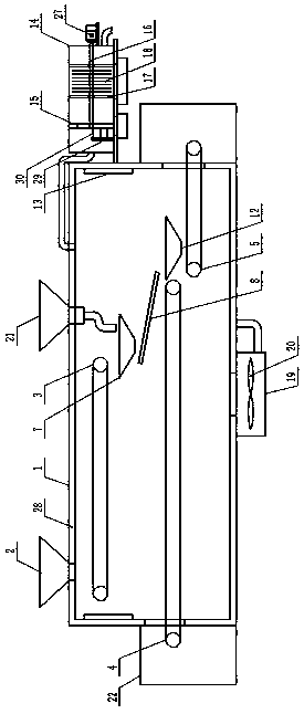
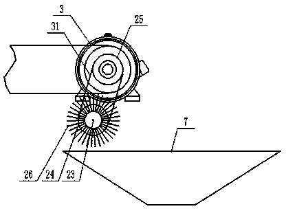
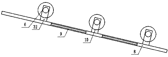
[0014] Embodiment 1: see figure 1 , figure 2 , image 3 , Figure 4 , a preparation device for a coal-water slurry additive provided by the present invention is now described, including a drying box 1, a first feeding funnel 2 is provided at the top of the drying box 1, and a There is a first conveying mechanism 3, the inner cavity of the drying box 1 is located below the position of the first conveying mechanism 3, and a second conveying mechanism 4 is provided, and the inner cavity of the drying box 1 is located below the position of the second conveying mechanism 4, a third conveying mechanism 5 is arranged below the position, and a grinding mechanism 6 is arranged between the discharge end of the first conveying mechanism 3 and the feeding end of the second conveying mechanism 4, and the grinding mechanism 6 is formed by the first set The inclined material guide plate 8 provided directly below the bin 7 and the first collecting bin 7, the vibrating filter screen 9 prov...

Embodiment 2

[0015] Example 2: see figure 1 , figure 2, the preparation device for a kind of coal-water slurry additive provided by the present invention is described now, and described first conveying mechanism 3, the second conveying mechanism 4, the 3rd conveying mechanism 5 are all existing device belt conveyors, and all are made of A group of rotating rollers, a conveyor belt and a driving motor set between the rotating rollers. The material conveying direction of the first conveying mechanism 3 is the same as that of the third conveying mechanism 5. The material conveying direction of the first conveying mechanism 3 The conveying direction is opposite to the material conveying direction of the second conveying mechanism 4, and a first feed opening is opened on the top of the drying box 1 and directly above the position corresponding to the feed end of the first conveying mechanism 3, and the first feed inlet is The feed funnel 2 is arranged corresponding to the position of the firs...

Embodiment 3

[0016] Embodiment 3: see figure 1 , figure 2 , image 3 , Figure 4 , the preparation device for a kind of coal-water slurry additive provided by the present invention will be described now, the first collection bin 7 and the second collection bin 12 are both hollow circular frustum-shaped and both upper and lower ends are open, and the first collection bin The cross-sectional area of ​​the upper port of the feed bin 7 and the second collection bin 12 is larger than the cross-sectional area of ​​the lower port and is set in an inverted trapezoidal shape. The first collection bin 7 is located below the discharge end of the first conveying mechanism 3, so Below the position of the first conveying mechanism 3 and above the position of the first collecting bin 7, a rotating shaft 23 is provided. One end of the rotating shaft 23 in the longitudinal direction is covered with a driven pulley 24. The driving motor of the drive motor is arranged near the position of the first colle...


PUM


Abstract

The invention discloses a preparation device for a coal water slurry additive. The preparation device comprises a drying box body, wherein a first feeding funnel is arranged at the top end of the drying box body, a first conveying mechanism, a second conveying mechanism and a third conveying mechanism are arranged in the inner cavity of the drying box body, and a grinding mechanism is arranged between the discharging end of the first conveying mechanism and the feeding end of the second conveying mechanism; and the grinding mechanism is composed of a first material collecting bin, an inclined material guiding plate, a vibration filtering net sieve, a grinding roller and a rotating motor, wherein a heating plate is arranged on the inner side end wall of the drying box body, a gas filtering box body is arranged on the outer side end wall of the drying box body, a filter frame, a screw rod, a movable frame and a water absorption layer are arranged in the filter box body, an air supply box body is arranged at the bottom of the outer side of the drying box body, and an air supply fan is arranged in the air supply box body.

Description

technical field [0001] The invention relates to the field of coal-water slurry additives, in particular to a preparation device for coal-water slurry additives. Background technique [0002] The drying process in the preparation process of coal-water slurry additives is related to its storage quality in the later stage. The existing drying equipment for coal-water slurry additives generally adopts airflow drying, and uses manual stacking and drying. If the materials are piled up into agglomerates, it will cause Insufficient drying of internal materials and low drying efficiency affect the quality of CWS additives; the high-heat gas in the drying equipment for CWS additives is directly discharged, which will not only make the operating environment of the equipment hot and humid, but also cause heat energy A large amount of waste; CWS additives need to be ground and screened for particle size in the preparation process. The grinding and screening is usually carried out with sp...

Claims


Application Information

Patent Timeline
Patent Type & Authority Applications(China)
IPC IPC(8): B02C4/02B02C4/28B02C23/14B07B1/28B01D53/26B01D46/00B65G45/18
CPCB02C4/02B02C4/286B02C23/14B07B1/28B01D53/26B01D46/00B65G45/18
Inventor 沈健何其慧沈佩章峻蒋雪峰莫宏
Owner 江苏合义化工新材料有限公司
Learn More