A crystallizer for continuous casting equipment

A mold and equipment technology, applied in the field of steel processing, can solve the problems of increasing the resistance of molten steel, unstable eddy current, uneven heat conduction of the mold, and achieve the effects of reducing the contact time, increasing the stability, and reducing the resistance.

Active Publication Date: 2020-12-08
博兴融智科技创新发展有限公司
View PDF5 Cites 0 Cited by
  • Summary
  • Abstract
  • Description
  • Claims
  • Application Information

AI Technical Summary

Problems solved by technology

[0003] The working principle of the existing crystallizer is as follows Figure 4 As shown, the molten steel is injected from the top of the mold, and then an appropriate amount of mold powder is added. After shaking, the mold powder falls between the mold and the billet shell, and under the cooling of the mold wall, it solidifies against the side of the mold wall to form a glass body or The solid slag film of the crystalline body maintains the state of liquid slag on the side of the billet shell, and then the molten steel is cooled and formed by a cooling device. When the molten steel is injected, the speed of injecting molten steel into the crystallizer increases as the casting speed increases. Large, resulting in a significant increase in the flow rate of molten steel flowing out of the water outlet, resulting in a sharp increase in the flow rate of molten steel in the mold and the turbulence of the meniscus, and the eddy current on the liquid surface is not stable, causing the liquid surface to be involved in mold slag during rotation. In the molten steel, and the rotational flow of the molten steel, it is easy to cause the thickness of the primary billet shell in the meniscus area of ​​the crystallizer to be uneven, and the tensile stress acting on the billet shell exceeds the high temperature allowable strength and strain of the steel, which occurs in the weak part of the billet shell. Stress concentration causes longitudinal cracks in molten steel, which affects the quality of rolled products. Severe longitudinal cracks will cause waste products or leakage accidents. At the same time, the rotating flow of the liquid surface increases the resistance of the molten steel when it rises, making the liquid slag layer too thick or If the thickness of the slag is too thin, the viscosity of the slag is not suitable, and the thickness of the slag film between the inflow shell and the copper wall is uneven, which further causes uneven heat conduction of the mold and leads to uneven thickness of the shell in some areas, which promotes the occurrence of longitudinal cracks and affects the quality of the final product.

Method used


Image

  • A crystallizer for continuous casting equipment
  • A crystallizer for continuous casting equipment
  • A crystallizer for continuous casting equipment

Examples


Embodiment Construction

[0018] The following will clearly and completely describe the technical solutions in the embodiments of the present invention with reference to the accompanying drawings in the embodiments of the present invention. Obviously, the described embodiments are only some, not all, embodiments of the present invention. Based on the embodiments of the present invention, all other embodiments obtained by persons of ordinary skill in the art without making creative efforts belong to the protection scope of the present invention.

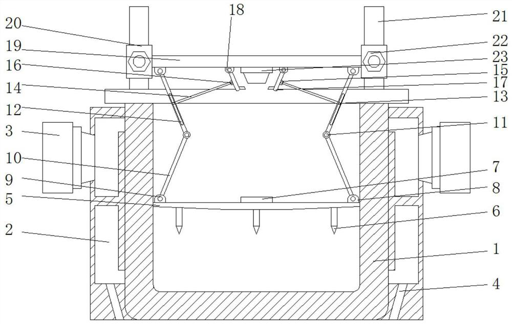
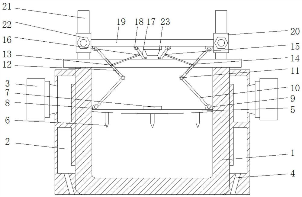
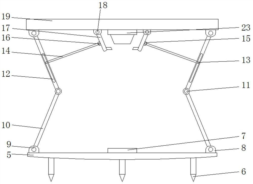
[0019] see Figure 1-3 , a crystallizer for continuous casting equipment, comprising a steel shell 1, a water distribution plate 2, a water inlet pipe 3, and a water outlet pipe 4, the water distribution plate 2 is installed on the outer wall of the steel structure shell 1, and the water inlet pipe 3 is installed on the water distribution plate 2, the water outlet pipe 4 is arranged at the bottom of the steel structure shell 1, and a cover plate 5 is installed...


PUM


Abstract

The invention relates to the technical field of steel processing, and discloses a crystallizing device for continuous casting equipment. The device comprises a steel component housing, a water distributing plate, a water inlet pipe and a water outlet pipe, wherein the water distributing plate is mounted on the outer wall of the steel component housing; the water inlet pipe is mounted on the water distributing plate; the water outlet pipe is arranged at the bottommost part of the steel component housing; a cover plate is mounted in the steel component housing; and a flow resisting rod is fixedly connected to the bottom part of the cover plate. According to the device, the molten steel surface flowing speed decreases due to gravitational pressing of the cover plate from the topmost part while the molten steel is poured, and thus the circumstance that rotary flowing of the molten steel surface is reduced; and meanwhile, the flow resisting rod is inserted into the molten steel surface, so that the molten steel surface is in contact with the flow resisting rod in the whole rotating process, and the rotating power of the molten steel surface is further reduced; the molten steel is kept stable during being poured, and the molten steel surface raises in a still state; protecting slags at the upper part of the molten steel surface uniformly fall between the crystallizing device and a blank housing, thus the raising resistance of the molten steel surface is reduced, and the quality of the molded molten steel reaches the standard.

Description

technical field [0001] The invention relates to the technical field of steel processing, in particular to a crystallizer for continuous casting equipment. Background technique [0002] The crystallizer is a continuous casting equipment that accepts the molten steel injected from the tundish and solidifies it into a solid slab shell according to the specified cross-sectional shape. It is the most critical part of the continuous casting machine. Casting machine capacity plays a decisive role. [0003] The working principle of the existing crystallizer is as follows Figure 4 As shown, the molten steel is injected from the top of the mold, and then an appropriate amount of mold powder is added. After shaking, the mold powder falls between the mold and the billet shell, and under the cooling of the mold wall, it solidifies against the side of the mold wall to form a glass body or The solid slag film of the crystalline body maintains the state of liquid slag on the side of the b...

Claims


Application Information

Patent Timeline
Patent Type & Authority Patents(China)
IPC IPC(8): B22D11/04B22D11/10
CPCB22D11/04B22D11/10
Inventor 苏雨
Owner 博兴融智科技创新发展有限公司
Why Eureka
Try Eureka