
Visual-based man-machine safety system of industrial mechanical arm

A technology for industrial machinery and safety systems, applied in manipulators, program-controlled manipulators, manufacturing tools, etc., can solve the problems of inability to monitor distances and blind spots in monitoring, and achieve the effects of improving safety, improving production efficiency, and reducing blind spots

Active Publication Date: 2019-09-20
FOSHAN KINGPENG ROBOT TECH CO LTD
View PDF12 Cites 35 Cited by
  • Summary
  • Abstract
  • Description
  • Claims
  • Application Information

AI Technical Summary

Problems solved by technology

Zhu Hongjie proposed a safety alarm mechanical claw of an industrial mechanical arm (Zhu Hongjie. A safety alarm mechanical claw of an industrial mechanical arm [P]. Chinese patent: CN108772848A, 2018-11-09.), which senses the mechanical arm through infrared light The distance between obstacles, but due to the relative position setting and the limitation of sensor layout, fast distance monitoring cannot be performed, and there may even be monitoring blind spots
Chen Xingchen, Xiao Nanfeng proposed a real-time avoidance planning and grasping system of industrial manipulator based on Kinect depth camera (Chen Xingchen; Xiao Nanfeng. Real-time obstacle avoidance planning and grasping system of industrial manipulator based on Kinect depth camera[P]. China Patent: CN108972549A, 2018-12-11.), the Kinect camera senses the surrounding environment of the manipulator, and detects and tracks dynamic obstacles. However, this method uses human skeleton information for collision detection. Dynamic obstacles cannot be identified only by capturing the human skeleton, so this method has certain limitations

Method used


Image

  • Visual-based man-machine safety system of industrial mechanical arm
  • Visual-based man-machine safety system of industrial mechanical arm
  • Visual-based man-machine safety system of industrial mechanical arm

Examples


specific Embodiment approach

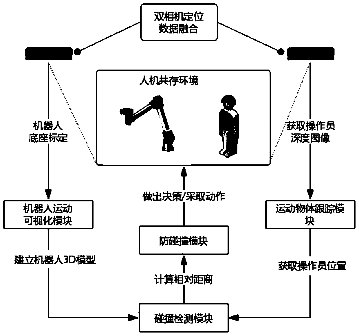
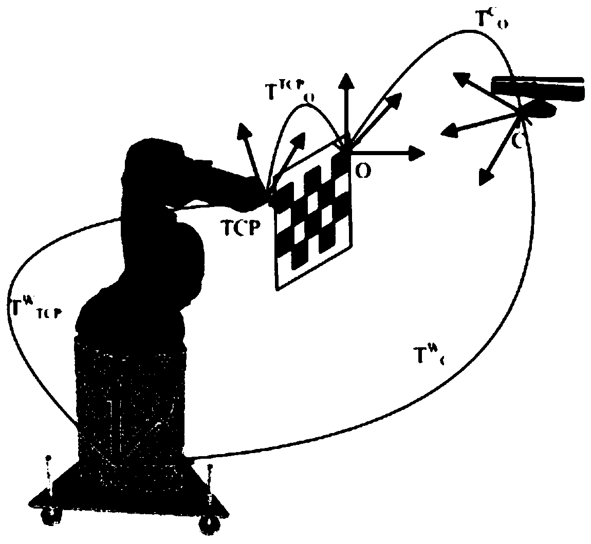
[0034] combine figure 1 , figure 2 , the specific implementation of the patent of the present invention is as follows:

[0035] The moving object tracking module uses the method of background difference to extract the foreground from the depth map based on the image of the manipulator workspace collected by the depth camera, and converts the depth map of the foreground into a point cloud image for clustering, and according to the number of point clouds and height information Extract the operator or other obstacles. The specific operation steps are as follows:

[0036] 1) First use the depth camera to capture the depth map of the robot's static environment (ie no people or any dynamic obstacles).

[0037] 2) Use the real-time urdf filter to process the depth map in step 1, and remove the robot itself from the depth map.

[0038] 3) Repeat steps 1 and 2 to obtain multiple depth maps, and then take the average value to reduce the influence of noise and use it as the environmen...


PUM


Abstract

The invention discloses a visual-based man-machine safety system of an industrial mechanical arm. The visual-based man-machine safety system of the industrial mechanical arm comprises a moving object tracking module used for capturing spatial positions of all moments of a moving object, a robot movement visualization module used for acquiring robot joint information and carrying out 3D visualization on a robot, a collision detection module used for calculating the minimum distance between a robot 3D model and an operator in the environment, and a collision avoidance module used for planning and correcting the robot motion trajectory; firstly, a system extracts image information of the operator in the environment through two kinect cameras, and data fusion is performed; then a current state of the robot is obtained, and the 3D model of the environment where the robot is located is constructed; then a shaft alignment bounding box method is used for carrying out the collision detection on the operator and the robot; and finally, according to a collision detection result, an anti-collision module can give an alarm to the operator and stop the robot or modify the trajectory of the robot, so that the robot can far away from the operator who is approaching.

Description

technical field [0001] The invention relates to a human-machine safety system of an industrial manipulator, in particular to a vision-based man-machine safety system of an industrial manipulator. Background technique [0002] In recent years, with the rapid development of robot technology and the continuous improvement of the mechanization and automation level of the production process, robots have liberated people from manual labor in many occasions. In the case of industrial applications, in order to ensure the safety of humans and robots, the robot usually has obstacles in its working area to create a physical separation between the robot and humans. Although this is the simplest and most effective method, it hinders the interaction between robots and humans because robots cannot adapt to unknown environments. Under the premise of guaranteeing human safety, humans and robots can safely coexist and share a workspace, which can give full play to the respective advantages o...

Claims


Application Information

Patent Timeline
Patent Type & Authority Applications(China)
IPC IPC(8): B25J9/16
CPCB25J9/1602B25J9/1679B25J9/1697
Inventor 欧林林来磊禹鑫燚吴加鑫金燕芳
Owner FOSHAN KINGPENG ROBOT TECH CO LTD
Learn More