
Bridge crane with safer utilization and wider applicability

An overhead crane, a technology of applicability, which is applied in the directions of walking overhead cranes, cranes, and traveling mechanisms, can solve the problems of large construction site impact, limited lifting area, and falling walking frames, and achieves safe operation and lifting. The effect of increasing the area and enhancing the adaptability

Pending Publication Date: 2019-09-20
厦门中起起重机有限公司
View PDF0 Cites 2 Cited by
  • Summary
  • Abstract
  • Description
  • Claims
  • Application Information

AI Technical Summary

Problems solved by technology

[0005] The present invention provides a bridge crane with safer use and wider applicability, so as to solve the problems of limited lifting area, large impact on construction site, and risk of walking frame falling off in most existing bridge cranes.

Method used


Image

  • Bridge crane with safer utilization and wider applicability
  • Bridge crane with safer utilization and wider applicability
  • Bridge crane with safer utilization and wider applicability

Examples


Embodiment approach 1

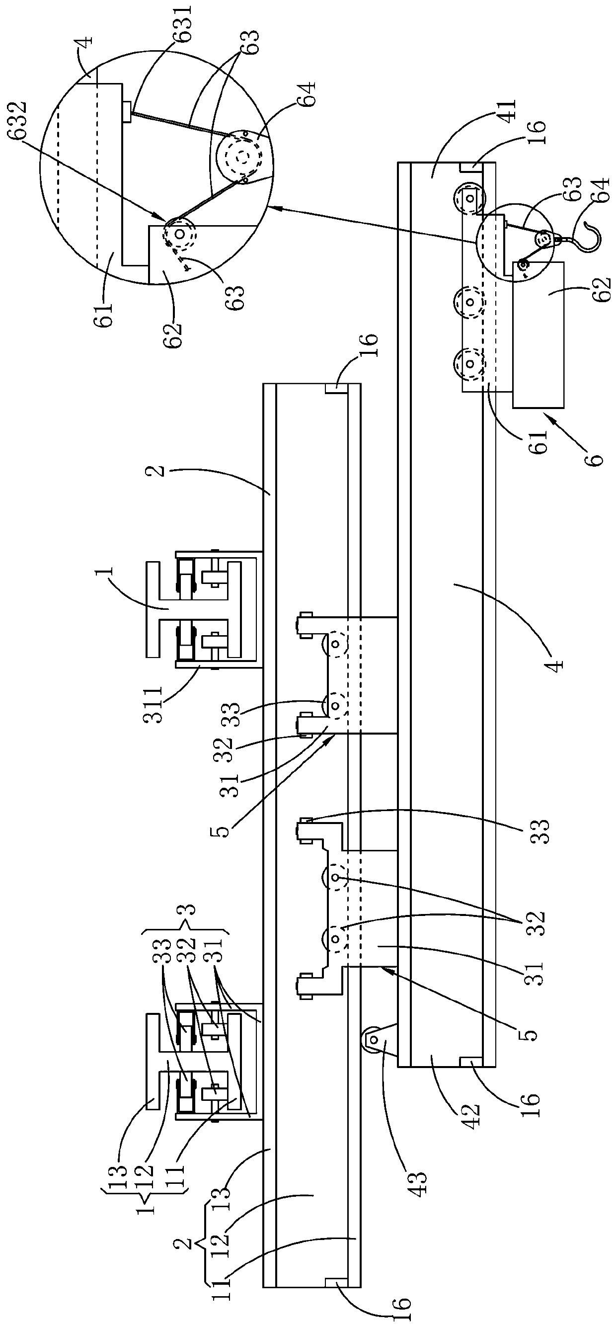
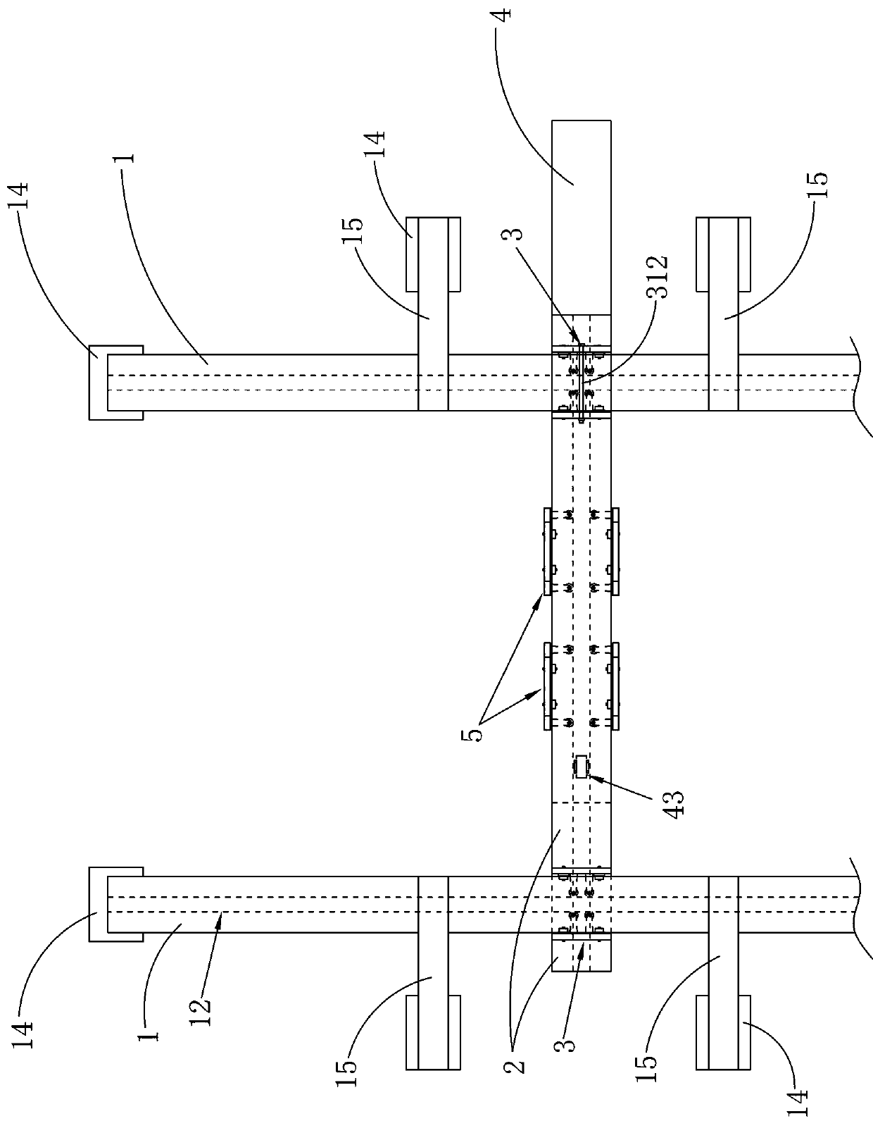
[0025] refer to figure 1 , figure 2 , a bridge crane with safer use and wider applicability, including a longitudinal main girder 1 and a cross girder 2, both of which are composed of a bottom plate 11, a connecting wall plate 12 and a top plate 13 which are sequentially fixed and connected as a whole, The cross-sections of the longitudinal main beam 1 and the cross beam 2 are both H-shaped; the longitudinal main beam 1 is fixedly assembled on the supporting carrier (such as figure 2 As shown, the support carrier is preferably a cement support column 14 standing on the ground, a metal skeleton 15 above the longitudinal main beam 1, etc.), the beam 2 is equipped with a longitudinal walking frame 3, and the beam 2 slides and is assembled on the Below the longitudinal girder 1.

[0026] Continue to refer to figure 1 , figure 2 , the above beam 2 is equipped with an extension beam 4, the extension beam 4 slides and is assembled under the beam 2 through the traverse frame 5,...

Embodiment approach 2

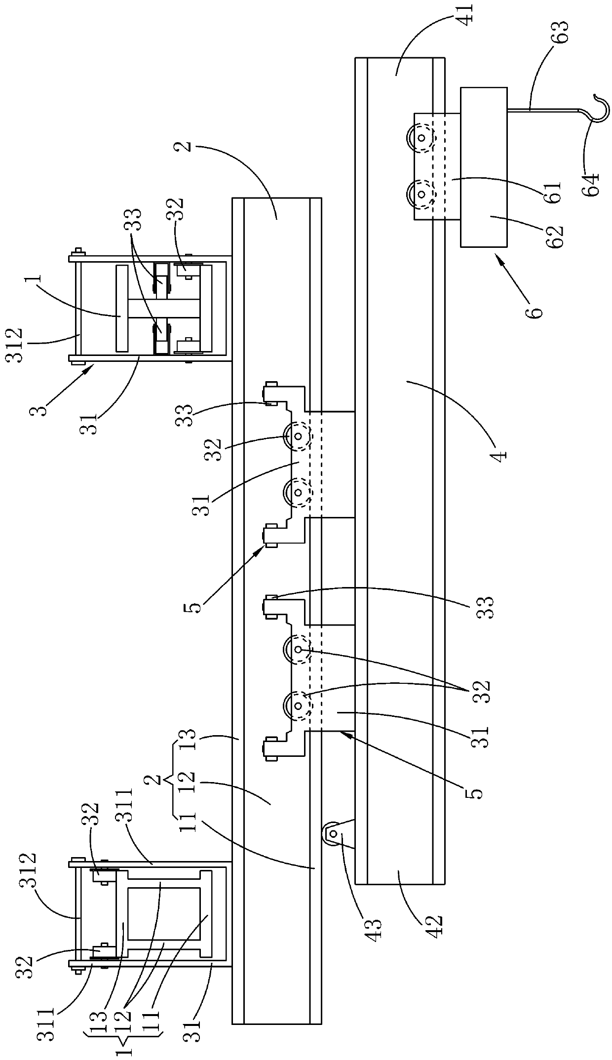
[0032] refer to image 3 , Figure 4 The installation frame 31 of the above-mentioned longitudinal walking frame 3 is U-shaped, and the two side plates 311 of the installation frame 31 are respectively extended upwards from the two sides of the above-mentioned longitudinal main beam 1, and the traveling wheels 32 of the above-mentioned longitudinal walking frame 3 are rotated with a fixed axis. Assembled on the side plate 311 , the traveling wheel 32 travels on the top surface of the top plate 13 of the longitudinal main beam 1 . The longitudinal traveling frame 3 and the top of the longitudinal main girder 1 slide, so that the load of the longitudinal traveling frame 3 is carried by the longitudinal main girder 1 as a whole (refer to figure 1 , when the traveling wheels 32 are walking on the bottom of the longitudinal girder 1, after the bottom plate 11 bears the load, the acting force on the connecting wall plate 12 is a downward pulling force, and the acting force of the c...


PUM


Abstract

The invention relates to a bridge crane with safer utilization and wider applicability. The bridge crane comprises a longitudinal main beam and a cross beam, wherein the cross section of the longitudinal main beam and the cross beam are in an I-shaped shape, the longitudinal main beam is fixedly assembled on a supporting carrier, and the cross beam is slidably assembled below the longitudinal main beam through a longitudinal traveling frame; the cross beam is provided with an extending beam, the extending beam is assembled below the cross beam in a sliding mode through transverse traveling frames, and the extending beam is provided with a lifting trolley used for lifting a lifting object; the longitudinal traveling frame and the transverse traveling frames respectively comprise a mounting frame, walking wheels, limiting wheels and a walking motor; and the limiting wheels slides along the extending direction of the length of a connecting wall plate in a rolling-contact manner, and the limiting wheels are used for limiting the mounting frames to shift along the width direction of s bottom plate. According to the bridge crane, through traveling and stretching operation of the extending beam, the bridge crane can expand the walking range of the lifting trolley in the extending direction of the cross beam by spanning supporting columns on a construction site, the separation probability of the traveling frames is effectively reduced, operation is safer, and the noise pollution is reduced.

Description

technical field [0001] The invention relates to the field of bridge cranes, in particular to a bridge crane with safer use and wider applicability. Background technique [0002] The bridge crane is a lifting device that is horizontally placed over the workshop, warehouse and stockyard for material lifting. The characteristic of the bridge crane is that it can realize the vertical lifting or horizontal movement of the heavy objects hanging on the hook or other pick-up devices in space. The bridge crane includes: lifting mechanism, large and small trolley running mechanism. Relying on the coordinated actions of these mechanisms, heavy objects can be lifted and transported in a certain cubic space. [0003] The beams of most existing bridge cranes are mostly supported by two longitudinally extending main beams on the left and right. The lifting trolleys on the beams can only lift heavy objects within the extension range of the beams. However, many existing factories need to b...

Claims


Application Information

Patent Timeline
Patent Type & Authority Applications(China)
IPC IPC(8): B66C17/04B66C11/16B66C9/08B66C9/16
CPCB66C17/04B66C11/16B66C9/08B66C9/16
Inventor 翟永刚
Owner 厦门中起起重机有限公司
Learn More