Pipe sinking pressure fillingconstruction method of cast-in-place pile

A construction method and technology of cast-in-situ piles, which are applied in sheet pile walls, foundation structure engineering, construction, etc., can solve problems affecting the forming quality of pile holes, poor pile foundation pile quality, and pile pipe subsidence, etc., and achieve stable force, The quality of the pile is good and the effect of improving the bearing capacity

Inactive Publication Date: 2019-09-20
深圳建中路桥工程有限公司
View PDF3 Cites 5 Cited by
  • Summary
  • Abstract
  • Description
  • Claims
  • Application Information

AI Technical Summary

Problems solved by technology

However, when hammering, the hammering force first acts on the pile tube, and then passes through the tube body of the pile tube to the coating, thereby causing the pile tube to sink. Since the inside of the pile tube is a hollow structure, the pile tube is During the process of bearing the hammer force, deformation and distortion may occur, which will affect the forming quality of the pile hole, which will lead to poor pile quality of the pile foundation

Method used


Image

  • Pipe sinking pressure fillingconstruction method of cast-in-place pile
  • Pipe sinking pressure fillingconstruction method of cast-in-place pile
  • Pipe sinking pressure fillingconstruction method of cast-in-place pile

Examples


Embodiment Construction

[0038] The present invention will be further described in detail below in conjunction with the drawings.

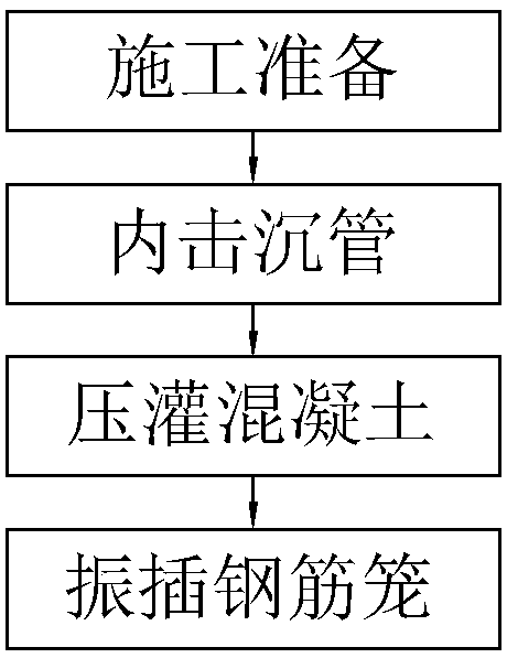
[0039] Such as figure 1 As shown, a cast-in-place pile sinking pipe pressure irrigation construction method includes the following steps:

[0040] S1 Construction preparation, first move the pile machine to the pile position for assembly and positioning, and then install the pile pipe on the pile machine.

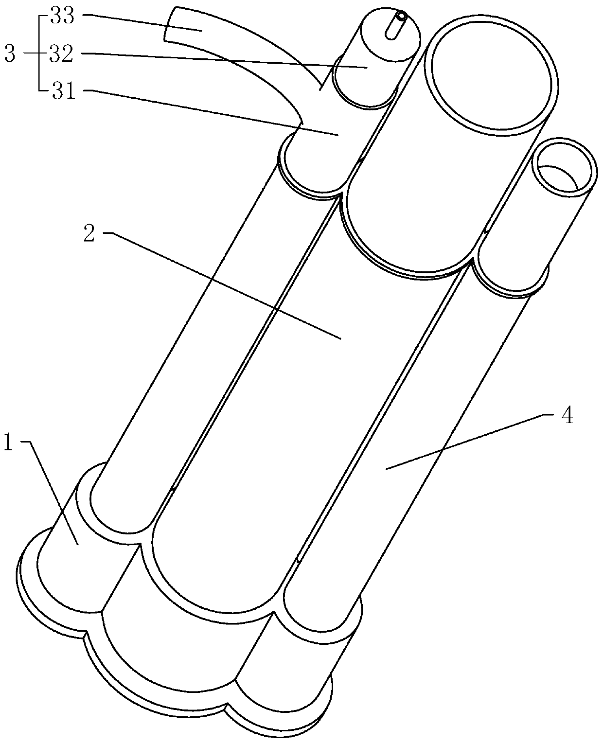
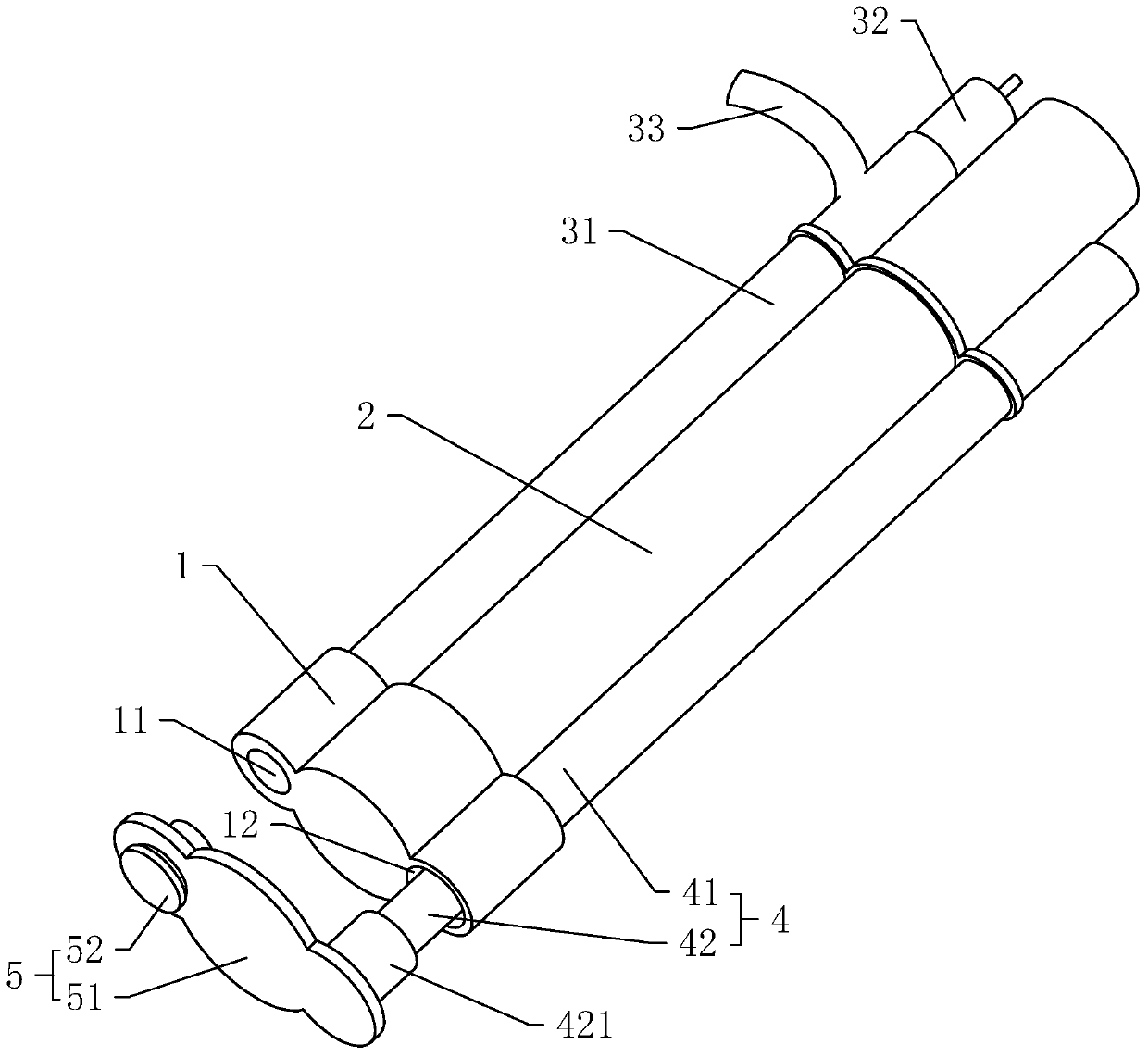
[0041] Such as figure 2 As shown, the pile pipe includes a bottom plate 1, a main pipe 2, a pouring pipe 3, and a protective pipe 4. The bottom plate 1 uses a flat metal plate. The bottom plate 1 must be straight so that the pile pipe can penetrate the soil layer. Make the bottom of the pile hole flatter, so that the pile foundation formed by pouring will have a higher bearing capacity.

[0042] The main pipe 2, the perfusion pipe 3, and the protective pipe 4 are all fixed to the bottom plate 1 by welding. After the bottom plate 1, the main pipe 2, the perfusion pipe 3 and th...


PUM


Abstract

The invention discloses a pipe sinking pressure fillingconstruction method of a cast-in-place pile, and relates to building technology.The pipe sinking pressure fillingconstruction method of the cast-in-place pile is used for solving the problem of poor quality of ordinary pressure-filled piles andcomprises the following steps that construction is prepared, a pile machine and a pile pipe are assembled in a pile position, and the pile pipe is kept vertical; asinking pipe is stricken inwardly, aninwardly stricken hammer directly acts on a bottom plate, so that the pile pipe sinks into a soil layer to form a pile hole; concrete is subjected to pressure filling, the concrete is poured under the bottom plate, and the pile pipe is pulled upwards to be separated from the pile hole; areinforcement cage is inserted in a vibration mode, the reinforcement cage is inserted into the pile hole to complete pile foundation construction; the hammering method directly applying the force to the bottom plate causes the pile pipe to be pulled during the process of penetrating the soil layer, so that the pile pipe is not prone to producing bending deformation under the action of the hammering force, and the pile hole forming quality is higher, meanwhile the pile pulling method of pushing the pile pipe to float by the poured concrete can always press the inner wall of the pile hole, so that the pile hole is also not prone to producing shrinkage during the floating of the pile pipe, and thus the pile foundation is better in pile quality.

Description

Technical field [0001] The invention relates to construction technology, in particular to a construction method of sinking pipe pressure irrigation for cast-in-place piles. Background technique [0002] All buildings need to drive ground piles before construction. Ground piles are basic components set in the soil. Their main function is to transfer the load of the building to the harder and denser underground soil structure. A deep foundation to alleviate the tilt and subsidence of buildings. [0003] At present, the Chinese invention patent with the authorized announcement number CN102286970B discloses a whole-process construction method of sinking pipe cast-in-place pile and its special device. The special device includes pile pipe and backing plate; pile pipe includes A, B and C pile pipes. . [0004] The above-mentioned cast-in-place pile equipment uses a pile machine to hammer the pile pipe so that the pile pipe penetrates into the soil layer. After the pile pipe reaches the r...

Claims


Application Information

Patent Timeline
Patent Type & Authority Applications(China)
IPC IPC(8): E02D15/04E02D5/34
CPCE02D5/34E02D15/04
Inventor 劳品勇潘俊超梅琪恩
Owner 深圳建中路桥工程有限公司
Why Eureka
Try Eureka