High-integration lightweight array radar antenna skeleton

A radar antenna, highly integrated technology, used in antennas, antenna parts, antenna supports/installation devices, etc., can solve the problems of excess safety margin, material waste, low heat dissipation efficiency, etc., to meet the overall bearing capacity and plane. Stiffness, smooth and beautiful appearance, good overall sealing effect

Active Publication Date: 2019-09-20
WUHAN BINHU ELECTRONICS
View PDF6 Cites 8 Cited by
  • Summary
  • Abstract
  • Description
  • Claims
  • Application Information

AI Technical Summary

Problems solved by technology

[0005] Generally speaking, in the design process of the existing vehicle-mounted array antenna skeleton, since its structural function requirements meet the installation and operation functions of the antenna and internal equipment, the requirements for its own rigidity and strength are very strict; for this reason, the traditional design scheme Thicker steel plates are often used in tailor-welded parts for local processing, which directly leads to excess safety margins, resulting in waste of materials, and the skeleton is heavy in weight, poor in appearance quality, and inconsistent with the overall structure
The functions of the traditional antenna frame structure are relatively limited. There is almost no consideration for sharing the cooling pipelines, installation positioning, and blind plug socket fixation of radar transceiver components and other equipment. The space for installation, connection, and maintenance of interconnection cables leads to a low level of functional integration of the antenna frame itself and a low level of integration of internal equipment layout.
[0006] Most of the transceiver components installed in the antenna frame of the existing antenna are air-cooled for heat dissipation, relying on the heat conduction between the wind and the surface of the transceiver component to take away heat, the heat dissipation efficiency is low, and the transceiver components cannot be densely arranged, and the antenna frame cannot effectively solve the heat dissipation problem of the transceiver component. Make the antenna bobbin bulky

Method used


Image

  • High-integration lightweight array radar antenna skeleton
  • High-integration lightweight array radar antenna skeleton
  • High-integration lightweight array radar antenna skeleton

Examples


Embodiment Construction

[0034] The present invention will be further described below in conjunction with drawings and embodiments.

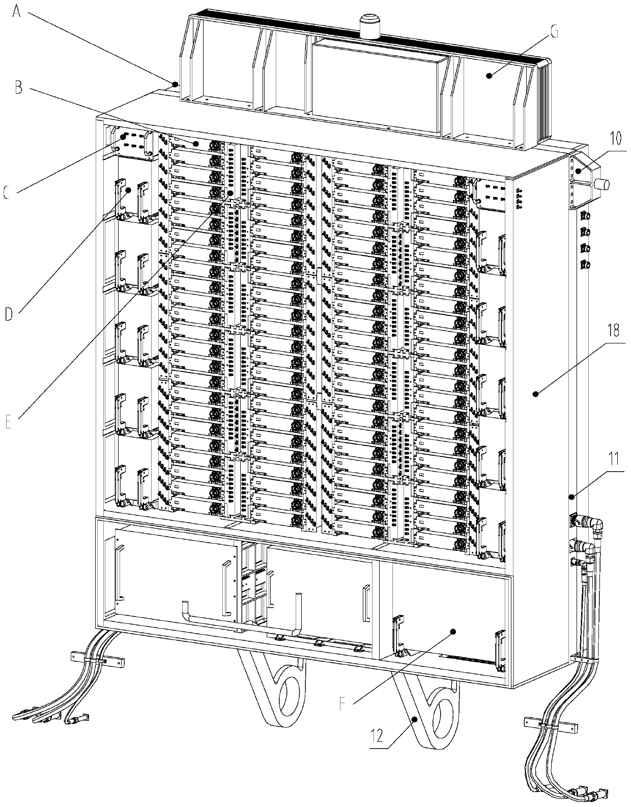
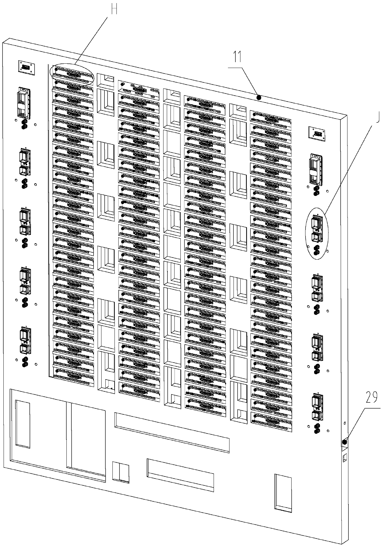
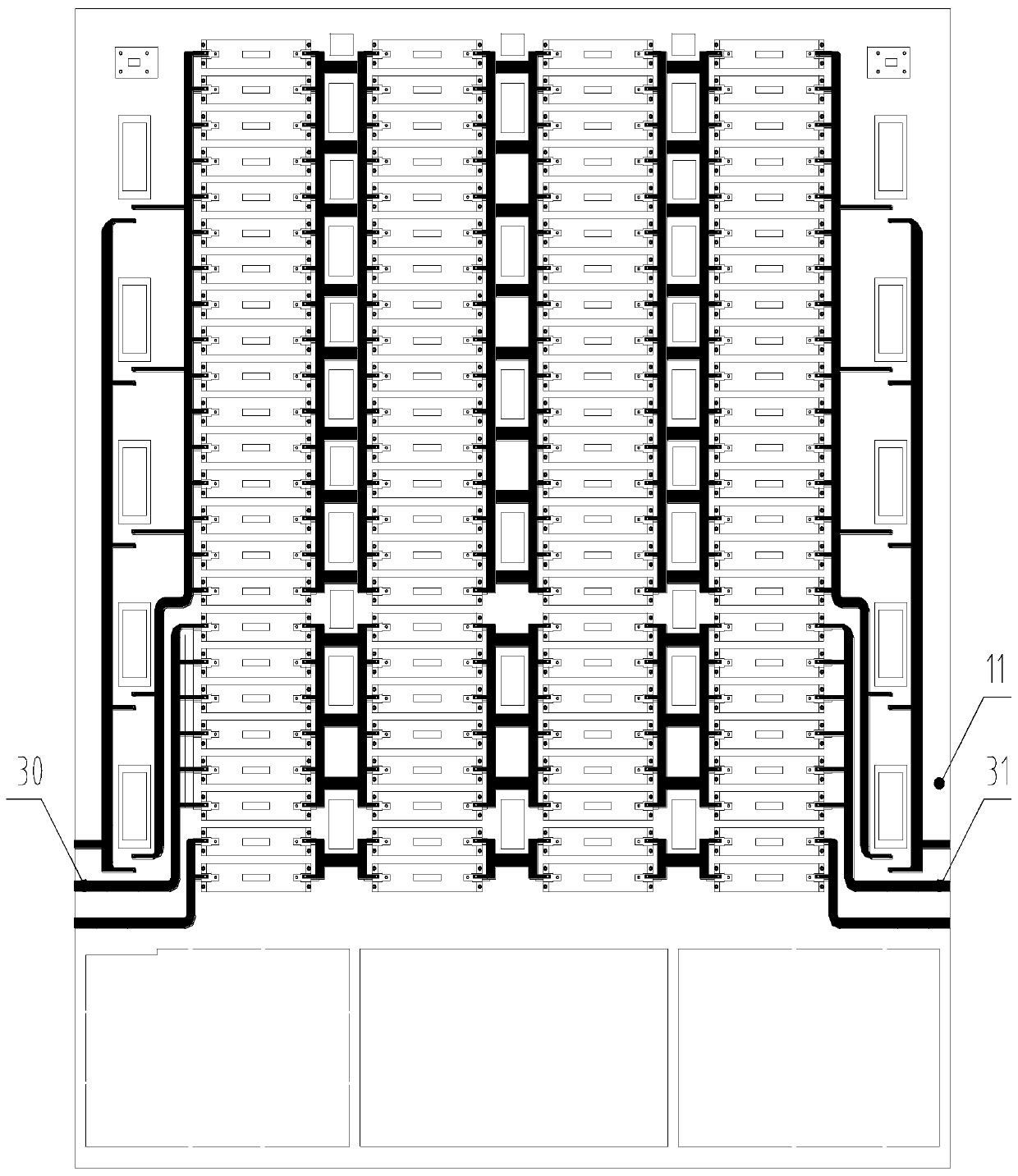
[0035] Such as Figure 1 to Figure 7 As shown, the highly integrated lightweight array radar antenna framework of the present invention includes a pitch screw support 10, a back plate 11, an antenna support 12 and an outer frame 18, an antenna longitudinal rib 19, and an antenna transverse rib 20, The bottom surface of the lower part of the backboard 11 is provided with an antenna support 12, the side of the middle part of the backboard 11 is provided with a pitch screw support 10, and the periphery of the backboard 11 is provided with an outer frame 18, which is connected to the antenna longitudinal rib 19 and the antenna transverse rib 20. Form the antenna skeleton. In the present invention, the antenna support 12 is connected to the rotating shaft on the antenna cart, the pitch screw support 10 is connected to the antenna pitch screw, and the antenna pitch screw pus...


PUM


Abstract

The invention relates to the field of radar antenna vehicles and particularly relates to a high-integration lightweight array radar antenna skeleton. An outer frame is arranged around a backplane. A liquid cooling water channel is arranged inside the backplane. The backplane is formed by an aluminum plate through primary processing. A coolant enters the backplane from a liquid inlet and exits from a liquid outlet. A plurality of liquid-cooled blind-mate plugs are arranged on the backplane. An antenna longitudinal rib plate, an antenna transverse rib plate, and an antenna unit mounting slot are disposed inside the outer frame. A cavity portion in the outer frame on the front side of the backplane divides the space inside the outer frame into electronic compartments by the antenna longitudinal rib plate and the antenna transverse rib plate. The lower space in the outer frame is provided therein with an extension compartment. The upper space in the outer frame is provided therein with a component compartment. The cavity portion in the outer frame on the back side of the backplane is provided therein with the antenna unit mounting slot. The antenna skeleton assembly of the invention has the characteristics of compact and reasonable layout, high integration, reliable structure, low weight, good rigidity, high precision, good maintainability and fast heat dissipation.

Description

technical field [0001] The invention relates to the field of radar antenna vehicles, in particular to a highly integrated light-weight array radar antenna frame. Background technique [0002] The radar antenna frame assembly is an extremely important part of the overall structure design of the radar. As the main frame supporting the antenna, feeder and related equipment, it is a key mechanism for bearing and transmitting environmental loads during transportation and work. Through the reasonable design and processing of the antenna skeleton assembly, the rigidity and the precision of the mounting surface can meet the precision indicators and functional requirements required by the radar antenna, feeder and related equipment to realize the radar; and through the integration of liquid cold plate, photoelectric liquid pipeline and The blind mating backplane completes the transmission and connection tasks of various optical and electrical signals and liquid cooling media for ant...

Claims


Application Information

Patent Timeline
Patent Type & Authority Applications(China)
IPC IPC(8): H01Q1/02H01Q1/12H01Q1/24
CPCH01Q1/02H01Q1/125H01Q1/24
Inventor 汪伟胡学艳赖三霞陈浩杜鹏赵世杰
Owner WUHAN BINHU ELECTRONICS
Why Eureka
Try Eureka