
Permanent-magnet traction motor

A traction and permanent magnet technology, applied in the direction of magnetic circuits, electric components, electrical components, etc., can solve the problems of easy vibration and noise, poor performance, and difficulty in ensuring the plane air gap of the stator and rotor, and achieve simple and easy manufacturing and assembly processes line, improve the power density per unit volume, and have a good shafting structure

Pending Publication Date: 2019-09-20
SHANGHAI GIE EM
View PDF0 Cites 1 Cited by
  • Summary
  • Abstract
  • Description
  • Claims
  • Application Information

AI Technical Summary

Problems solved by technology

[0003] The existing double-coil radial flux structure traction motor needs to make inner and outer slots on the same stator, so the manufacturing process is not good and the structure is poor, and two sets of AC windings are assembled at the same time. Electromagnetic field coupling interference produces more harmonic clutter, resulting in increased vibration and noise. Although the torque per unit volume is improved, the performance is not good
[0004] In the existing multi-disk axial flux structure traction motor, due to the large suction force in the axial direction of the stator and rotor, it is necessary to select a larger bearing, and the life of the bearing is shortened. In addition, the plane air gap between the stator and rotor is also Difficult to guarantee, also prone to problems such as vibration and noise

Method used


Image

  • Permanent-magnet traction motor
  • Permanent-magnet traction motor
  • Permanent-magnet traction motor

Examples


Embodiment 1

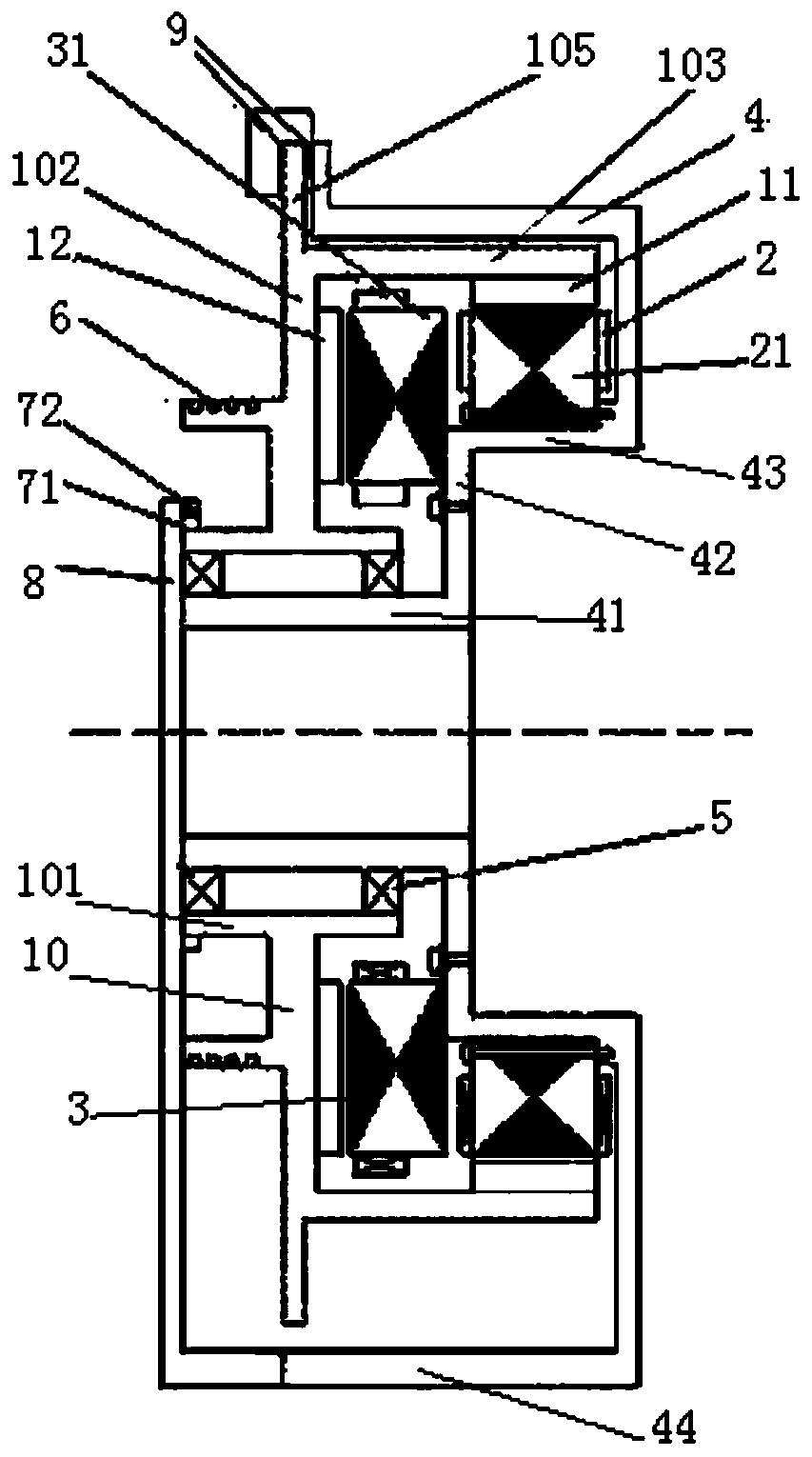
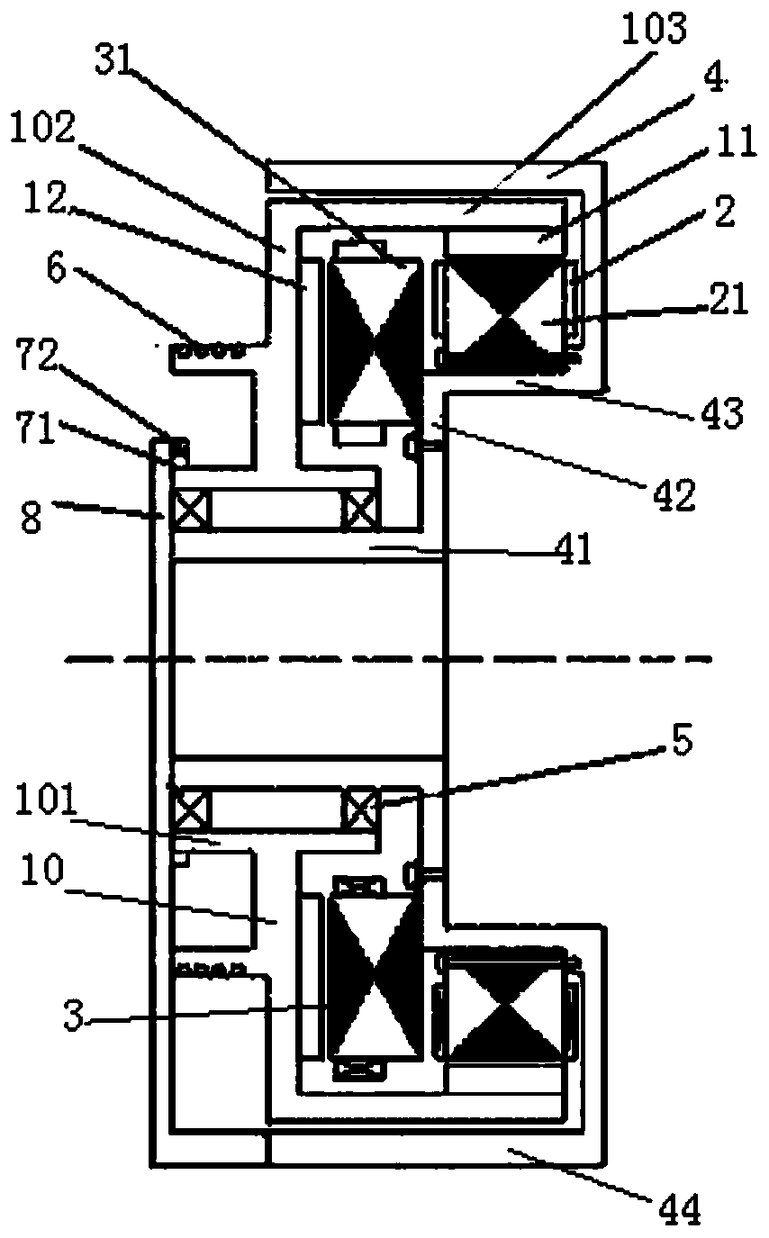
[0050] Such as figure 1 and figure 2 As shown, the permanent magnet traction motor includes a rotor part, a first stator 2, a second stator 3 and a frame 4;

[0051] The rotor part includes a rotor bracket 10, a first magnet 11 and a second magnet 12;

[0052] The rotor bracket 10 includes a rotor inner tube part 101, a rotor ring plate part 102 and a rotor outer tube part 103;

[0053] The machine base 4 includes an inner tube portion 41 of the machine base, a ring plate portion 42 of the machine base, and an outer tube portion 43 of the machine base;

[0054] The inner tube part 101 of the rotor is in the shape of a round tube; the ring plate part 102 of the rotor is in the shape of a ring; the outer tube part 103 of the rotor is in the shape of a round tube;

[0055] The inner tube part 41 of the machine base is in the shape of a round tube; the ring plate part 42 of the machine base is in the shape of a ring; the outer tube part 43 of the machine base is in the shape o...

Embodiment 2

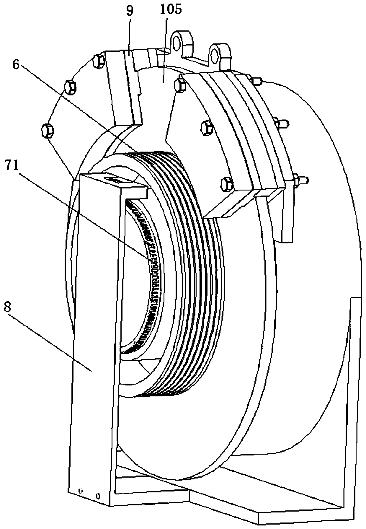
[0069] Based on the permanent magnet traction motor of the first embodiment, the left side of the rotor ring plate portion 102 of the rotor bracket 10 is integrally formed with a round tubular traction sheave portion 6 .

[0070] Embodiment two

[0071] Based on the permanent magnet traction motor of Embodiment 1, a ring-shaped rotor brake part 105 is once formed outward along the outer edge of the rotor ring plate part 102;

[0072] The brake pads 9 are located at the rotor brake part 105, and the left side and / or the right side of the rotor brake part 105 are used as braking surfaces to form a disc brake structure.

Embodiment 3

[0074] Based on the permanent magnet traction motor of Embodiment 1, the base 4 further includes a housing part 44 of the base;

[0075] The right end of the outer shell part 44 of the machine base is fixedly connected with the right end of the outer tube part 43 of the machine base;

[0076] The frame shell part 44 is sleeved on the outer tube part 103 of the rotor;

[0077] The brake is fixed on the shell part 44 of the machine base, the brake pad is in an arc shape, and the outer wall of the outer tube part 103 of the rotor is used as a braking surface to form a drum brake structure.


PUM


Abstract

The invention discloses a permanent-magnet traction motor. A ring of second magnet steel is uniformly attached to the right plate surface of a rotor ring plate part in an N-S alternating manner, the toothed slots of a second stator core with a corresponding part fixed on a frame adopt a radial structure, there is a planar air gap between the second stator core and the second magnet steel, and electromechanical energy conversion is carried out in an axial magnetic flux mode. A ring of first magnet steel is uniformly attached to the inner wall of a rotor outer pipe part in an N-S alternating manner, the toothed slots of a first stator core with a corresponding part fixed on the frame adopt an axial structure, there is an annular air gap between the first stator core and the first magnet steel, and electromechanical energy conversion is carried out in a radial magnetic flux mode. By using the permanent-magnet traction motor, there will no electromagnetic interference caused by electromagnetic field coupling in the same stator. The permanent-magnet traction motor has the advantages of compact structure, high power density per unit volume, high load carrying capacity, heavy load, good shafting structure, more stable force and simple manufacturing and assembling process.

Description

technical field [0001] The invention relates to motor technology, in particular to a permanent magnet traction motor. Background technique [0002] The traction motors of elevators and other equipment need to use large-load, high-power-density, compact permanent-magnet traction motors. Most of the existing large-load, high-power-density, compact permanent-magnet traction motors use double coils Radial flux structure or multi-disk axial flux structure. [0003] The existing double-coil radial flux structure traction motor needs to make inner and outer slots on the same stator, so the manufacturing process is not good and the structure is poor, and two sets of AC windings are assembled at the same time. Electromagnetic field coupling interference produces more harmonic clutter, resulting in increased vibration and noise. Although the torque per unit volume is improved, the performance is not good. [0004] In the existing multi-disk axial flux structure traction motor, due t...

Claims


Application Information

Patent Timeline
IPC IPC(8): H02K16/04H02K1/27H02K1/30H02K7/102H02K11/21H02K1/16
CPCH02K16/04H02K1/2713H02K1/2753H02K1/30H02K7/102H02K11/21H02K1/16H02K2201/03H02K2201/12
Inventor 屈义
Owner SHANGHAI GIE EM
Learn More