A TV display with depth of field

A display and TV technology, which is applied in the field of depth-of-field TV displays, can solve the problems of image stereoscopic effect, image clarity, and poor 3D effect, etc., and achieve the effects of enhancing image stereoscopic effect, improving anti-glare effect, and improving image depth

Active Publication Date: 2021-08-03
广州市粤祥电子科技有限公司
View PDF11 Cites 0 Cited by
  • Summary
  • Abstract
  • Description
  • Claims
  • Application Information

AI Technical Summary

Problems solved by technology

[0003] When people use the LCD screen, they often find that the 3D effect of the image is poor and the stereoscopic effect is insufficient. It has little to do with the 3D glasses worn. At the same time, the difference in the refraction structure of some LCD gratings has a huge impact on the three-dimensional effect of the image, and at the same time, it also directly affects the clarity of the image.

Method used


Image

  • A TV display with depth of field
  • A TV display with depth of field
  • A TV display with depth of field

Examples


Embodiment 1

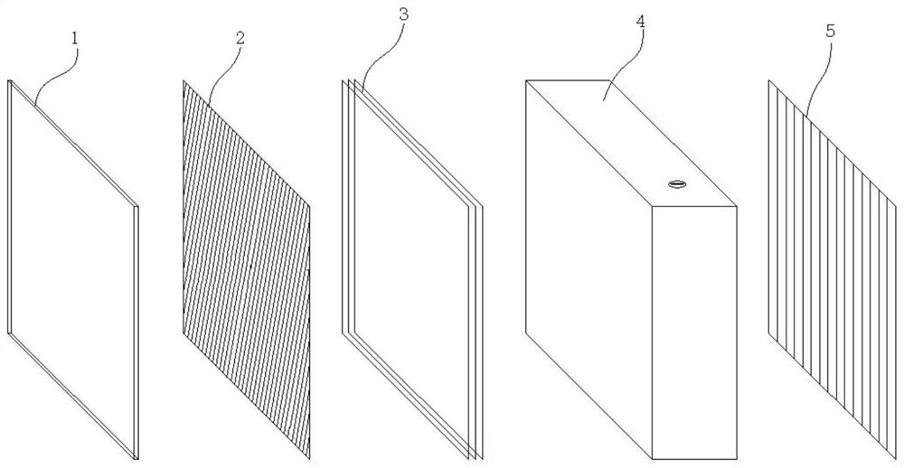
[0031] A depth-of-field television display is characterized in that it comprises a liquid crystal screen, a grating, a polarizing glass, a depth-of-field device and a polarizing film, and the liquid crystal screen, the grating, the polarizing glass, the depth-of-field device and the polarizing film are compounded in sequence.

[0032] In this embodiment, the image light emitted by the liquid crystal screen first passes through the grating refraction structure to form a three-dimensional image effect, and then passes through the polarizing glass to eliminate interference light and glare. The depth of the displayed virtual image formed by the image light is deepened, the depth of the image is enhanced, and the three-dimensional effect is enhanced. Finally, the image is displayed after being polarized by the polarizing film.

Embodiment 2

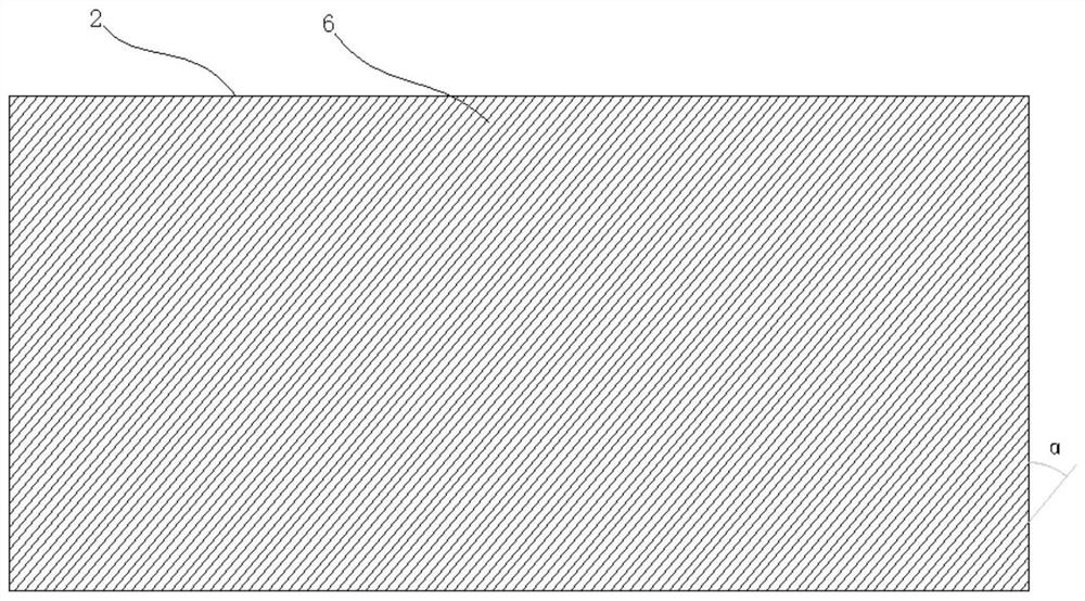
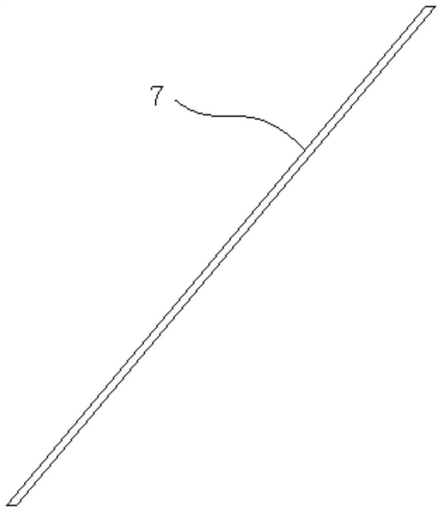
[0034] Embodiment 1 The front of the grating is provided with a plurality of obliquely arranged notches, and the notches are arranged in parallel, and there is one grating unit between two adjacent notches, and the notch and the vertical The angle in the vertical direction is the slope angle of the grating, and the slope angle of the grating is α, and the α is 15-65°;

[0035] Wherein, the grating unit is composed of a transmission arc surface in the middle and reflection surfaces on both sides of the transmission arc surface, and the notch is V-shaped to form reflection surfaces on both sides of the transmission arc surface, and the transmission arc surface is arc-shaped , the included angle between the reflective surface and the V-shaped symmetry line formed by the notch is β, and the β is 5-10.

[0036] In this embodiment, the notches are arranged obliquely to form obliquely parallel grating units, thereby adjusting the columnar arrangement refraction structure of the image...

Embodiment 3

[0040] The polarizing glass described in Embodiment 1 is formed by laminating the substrate, the second polarizing film and the reflective see-through film through pressure-sensitive adhesive;

[0041] Wherein, the substrate is one of optical glass, optically strengthened glass or TFT glass, and before bonding and compounding the polarizing film, the two sides of the polarizing film need to be subjected to AG treatment and AR treatment respectively, and the surface subjected to AR treatment It is the surface where the polarizing film is bonded to the substrate, and the AG-treated surface is the surface where the polarizing film and the reflective see-through film are bonded. The transmission direction and reflection direction of the reflective see-through film are unified, and are all opposite to the direction of the substrate.

[0042] The polarizing glass of this embodiment is designed according to the optical principle of the polarizing film. When the image light is perpendi...


PUM


Abstract

A depth-of-field TV display disclosed by the present invention comprises a liquid crystal screen, a grating, a polarizing glass, a depth-of-field device, and a polarizing film. The structure can be adjusted, and it has a reflective surface to reflect local image light. Polarized glass has high light transmittance, low reflectivity, good polarization effect, and uniform light dispersion, which can greatly eliminate interference light and glare, improve anti-glare effect and high image quality definition, and increase the brightness, the depth of field device can make the depth of the displayed virtual image deepened, enhance the depth of image, and enhance the three-dimensionality of the image. advantage.

Description

technical field [0001] The invention relates to the technical field of optical imaging equipment, in particular to a depth-of-field television display. Background technique [0002] Most of the TV monitors used today are liquid crystal screens, and the two sides of most liquid crystal screens pass through composite polarizing films to eliminate interfering light (including partial polarized light), and then display the image that people want to display. [0003] When people use the LCD screen, they often find that the 3D effect of the image is poor and the stereoscopic effect is insufficient. It has little to do with the 3D glasses worn. At the same time, the difference in the refraction structure of some LCD gratings has a huge impact on the three-dimensional effect of the image, and at the same time, directly affects the clarity of the image. Contents of the invention [0004] The present invention aims at the above problems, thereby disclosing a TV display with depth o...

Claims


Application Information

Patent Timeline
Patent Type & Authority Patents(China)
IPC IPC(8): H04N5/64H04N21/41H04N13/337G02F1/1335
CPCG02F1/133528H04N5/64H04N21/4122H04N13/337
Inventor 李道礼
Owner 广州市粤祥电子科技有限公司
Why Eureka
Try Eureka