
Servo actuator

A servo actuator and sensor technology, applied in the field of servo actuators, can solve the problems of large space occupation, high friction force, complex overall structure, etc., and achieve the effects of easy mass production, compact and reasonable arrangement, and good workmanship

Active Publication Date: 2019-09-24
JIANGSU HENGLI HYDRAULIC
View PDF10 Cites 3 Cited by
  • Summary
  • Abstract
  • Description
  • Claims
  • Application Information

AI Technical Summary

Problems solved by technology

[0002] In the prior art, commonly used ordinary hydraulic cylinders use low-friction sealing rings and guiding structures to achieve low-friction requirements. Among them, the sealing material is filled with PTFE, and the guiding structure is made of soldered copper, inlaid copper sleeves or nylon sleeves. Hydraulic cylinders have high friction and poor anti-eccentric load capability. High-frequency use is prone to leakage due to wear and tear due to heat generation, and the frequency response is low (generally below 15HZ)
In addition, according to the principle of hydrostatic bearings, a certain flow of oil first passes through the throttle valve (fixed throttle port), and then passes into the oil pad cavity (variable throttle port). Split design, the oil cushion cavity is designed in the inner hole of the guide sleeve, and 4 or 6 oil circuits are separated to connect with 4 or 6 corresponding throttle valves (the number corresponds to the static pressure oil chamber), but the overall structure is complicated and the tube The road layout is cumbersome, takes up a lot of space, is not suitable for mass production, and has poor versatility

Method used


Image

  • Servo actuator
  • Servo actuator
  • Servo actuator

Examples


Embodiment Construction

[0035] Embodiments of the present invention are described in detail below, examples of which are shown in the drawings, wherein the same or similar reference numerals designate the same or similar elements or elements having the same or similar functions throughout. The embodiments described below by referring to the figures are exemplary only for explaining the present invention and should not be construed as limiting the present invention.

[0036] In describing the present invention, it should be understood that the terms "center", "longitudinal", "transverse", "length", "width", "thickness", "upper", "lower", "front", " Back", "Left", "Right", "Vertical", "Horizontal", "Top", "Bottom", "Inner", "Outer", "Clockwise", "Counterclockwise", "Axial", The orientation or positional relationship indicated by "radial", "circumferential", etc. is based on the orientation or positional relationship shown in the drawings, and is only for the convenience of describing the present invent...


PUM


Abstract

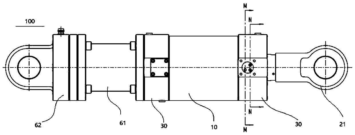
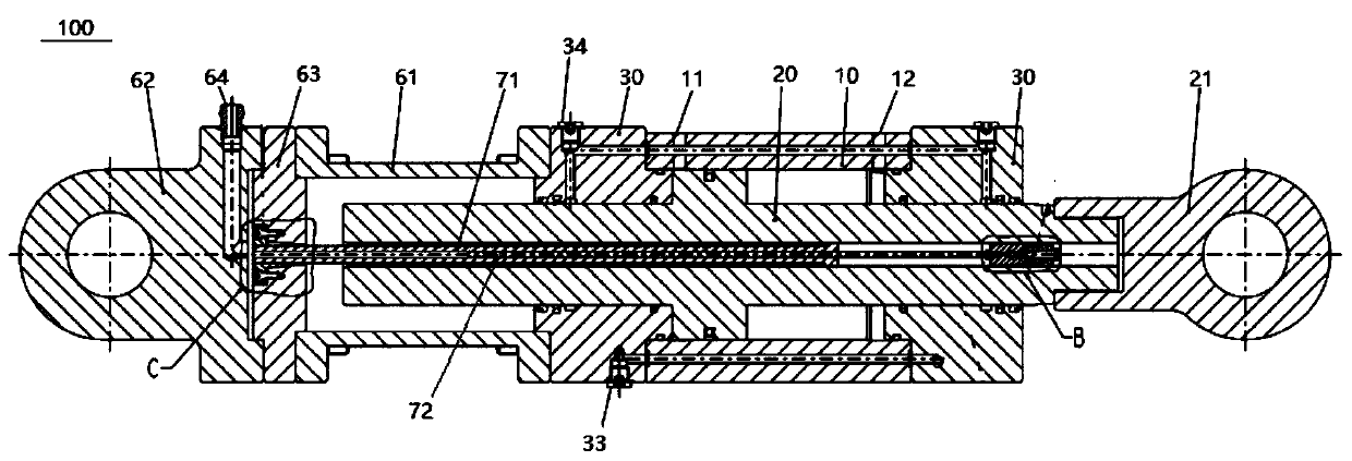
The invention provides a servo actuator. The servo actuator comprises a cylinder barrel, a piston rod, two end covers, a pressing block, a throttling valve, a cylinder bottom assembly and a sensor assembly, wherein a first mounting cavity which is axially through is defined in the cylinder barrel; at least one part of the piston rod is movably arranged in the first mounting cavity along the axial direction of the piston rod; the two end covers are arranged at the two ends of the cylinder barrel correspondingly, a column-shaped structure which is coaxial arranged is formed by two end covers and each end cover is provided with a guide channel which is through along the axial direction, the two ends of the piston rod correspondingly penetrate through the guide channel to extend out of the first mounting cavity, at least one groove communicating with the guide channel is formed in the outer wall surface of each end cover, and each end cover is provided with a second oil inlet communicating with the groove and a second oil outlet communicating with the guide channel; and the pressing block is arranged on the outer wall surface of each end cover and matched with the corresponding groove to define a static pressure oil chamber. According to the embodiment of the servo actuator, the structure is simple, the arrangement is compact and reasonable, the mounting space is saved, the low friction can be realized, and the anti-loading capability is achieved.

Description

technical field [0001] The invention relates to the technical field of hydraulic cylinders, in particular to a servo actuator. Background technique [0002] In the prior art, commonly used ordinary hydraulic cylinders use low-friction sealing rings and guiding structures to achieve low-friction requirements. Among them, the sealing material is filled with PTFE, and the guiding structure is made of soldered copper, inlaid copper sleeves or nylon sleeves. The hydraulic cylinder has high friction and poor anti-eccentric load capacity. It is easy to cause leakage due to heat generation and wear at high frequency use, and the frequency response is low (generally below 15HZ). In addition, according to the principle of hydrostatic bearings, a certain flow of oil first passes through the throttle valve (fixed throttle port), and then passes into the oil pad cavity (variable throttle port). Split design, the oil cushion cavity is designed in the inner hole of the guide sleeve, and 4...

Claims


Application Information

Patent Timeline
Patent Type & Authority Applications(China)
IPC IPC(8): F15B15/14F15B15/28
CPCF15B15/14F15B15/1438F15B15/149F15B15/2815F15B15/2892
Inventor 邱永宁张毅徐剑叶菁
Owner JIANGSU HENGLI HYDRAULIC
Learn More