Supercharge Your Innovation With Domain-Expert AI Agents!

Optical transceiver module and optical receiving assembly

A technology of light receiving components and light transmitting components, applied in optical components, light guides, optics, etc., can solve the problems of increasing signal beam insertion loss and return loss, adverse signal transmission quality, etc., to reduce insertion loss and return loss, improve Transmission rate, the effect of simplifying the production process

Active Publication Date: 2019-09-24
ZHUHAI FTZ OPLINK COMM +1
View PDF7 Cites 1 Cited by
  • Summary
  • Abstract
  • Description
  • Claims
  • Application Information

AI Technical Summary

Problems solved by technology

This light-receiving subassembly structure requires the introduction of lenses, optical waveguide components, and lens arrays. The signal beam input from the fiber optic socket needs to be coupled multiple times before reaching the optical sensing element, which increases the insertion loss and return loss of the signal beam. Not conducive to improving the quality of signal transmission

Method used


Image

  • Optical transceiver module and optical receiving assembly
  • Optical transceiver module and optical receiving assembly
  • Optical transceiver module and optical receiving assembly

Examples


Embodiment Construction

[0018] While the invention may readily manifest in different forms of embodiments, only a few specific embodiments have been shown in the drawings and will be described in detail in this specification, with the understanding that the specification should be considered as the These are exemplary illustrations of the principles of the invention and are not intended to limit the invention to what is described herein.

[0019] Thus, a feature indicated in this specification will be used to describe one of the features of an embodiment of the invention, not to imply that every embodiment of the invention must have the described feature. Furthermore, it should be noted that this specification describes a number of features. Although certain features may be combined to illustrate possible system designs, these features may also be used in other combinations not explicitly described. Thus, the illustrated combinations are not intended to be limiting unless otherwise stated.

[0020]...


PUM


Abstract

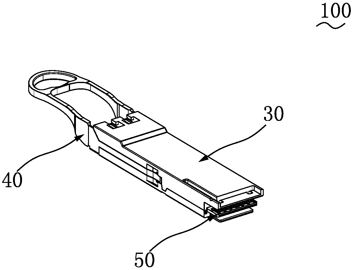
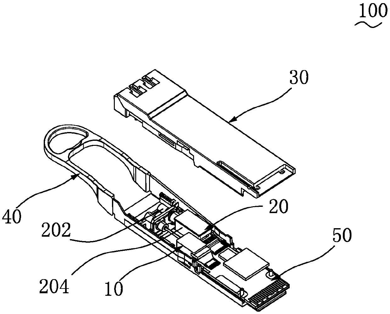
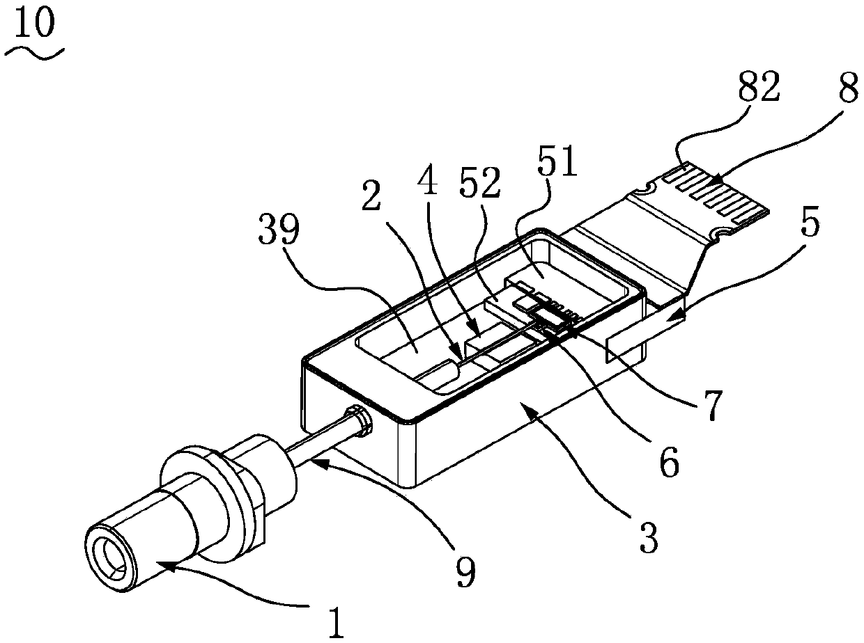
Disclosed are an optical transceiver module and an optical receiving assembly. The optical receiving assembly includes an optical fiber socket for receiving signal light, an optical fiber which is provided with a receiving end, an emitting end and a connection section between the receiving end and the emitting end, wherein the receiving end is fixed to the optical fiber socket and the emitting end is provided with a reflection inclined plane, and a shell which is provided with an accommodation cavity. The connection section and the emitting end of the optical fiber extend into the accommodation cavity. A fixing base and a circuit board are arranged in the accommodation cavity. The fixing base is provided with a fixing groove. The connection section of the optical fiber is correspondingly fixed to the fixing groove. A photo-detector and an amplifier are arranged on the circuit board. The photo-detector is arranged under the emitting end of the optical fiber. The signal light input from the receiving end of the optical fiber is reflected by the reflecting inclined plane of the optical fiber, enters the photo-detector and then is converted into an electrical signal. The electrical signal is amplified by the amplifier and then output to the outside. The optical transceiver module and the optical receiving assembly help to reduce the insertion loss and return loss of the signal light and increase the transmission rate.

Description

technical field [0001] The invention relates to a light receiving component, in particular to a light receiving component suitable for an optical transceiver module and beneficial to improving signal transmission quality. Background technique [0002] Chinese patent CN201410466751.2 discloses a light-receiving subassembly, which includes: a housing; a substrate, set in the housing; an optical fiber socket, located on one side of the housing, the optical fiber socket includes a first end and a second end, the first end is used to receive an optical fiber, the optical fiber is used to transmit a first light beam, and guide the first light beam to the second end; a lens is arranged in the housing, And adjacent to the second end; a plurality of optical sensing elements are arranged on the substrate; an optical waveguide element is arranged on the substrate and is located between the lens and the optical sensing elements, and the optical waveguide element includes an input end a...

Claims


Application Information

Patent Timeline
Patent Type & Authority Applications(China)
IPC IPC(8): G02B6/42
CPCG02B6/4246G02B6/428
Inventor 胡荣平吉勇孙涛程进龚声福谢光明
Owner ZHUHAI FTZ OPLINK COMM
Features
  • R&D
  • Intellectual Property
  • Life Sciences
  • Materials
  • Tech Scout
  • Unparalleled Data Quality
  • Higher Quality Content
  • 60% Fewer Hallucinations
Learn More