
Quick clamping flat tongs

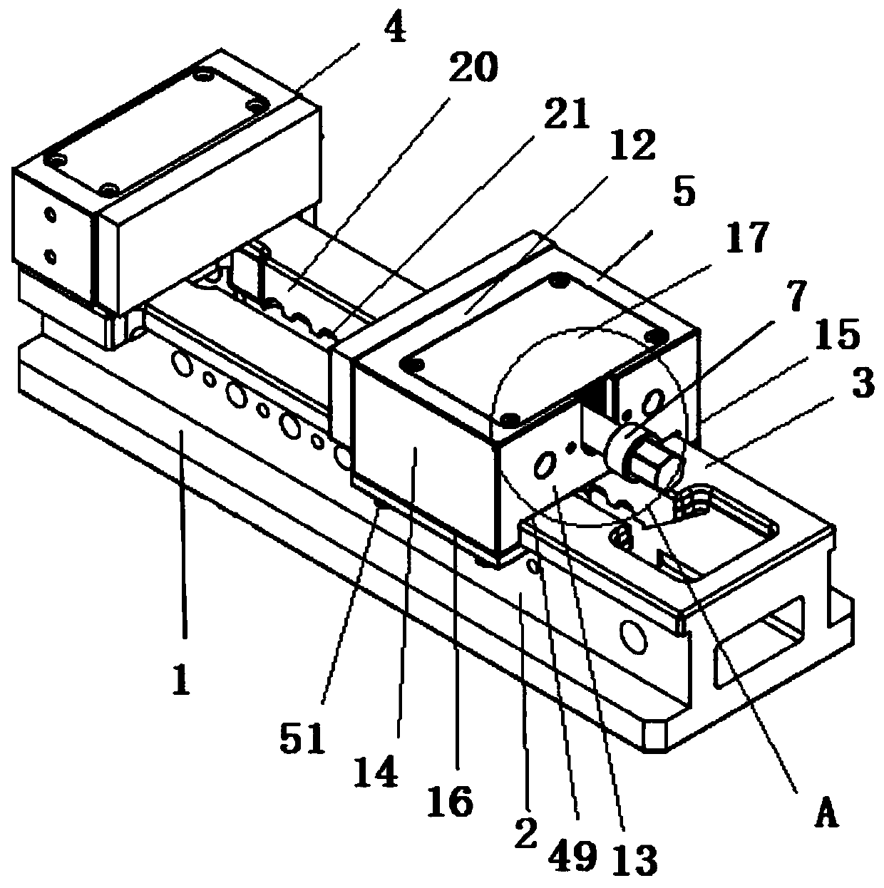
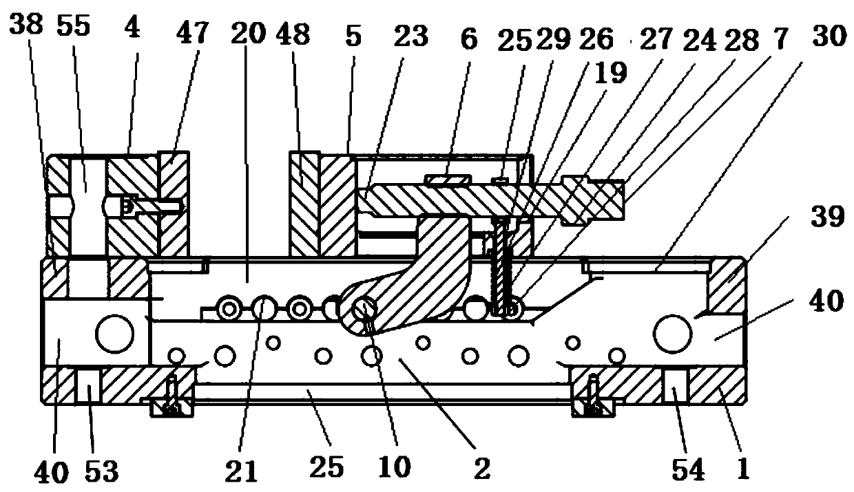
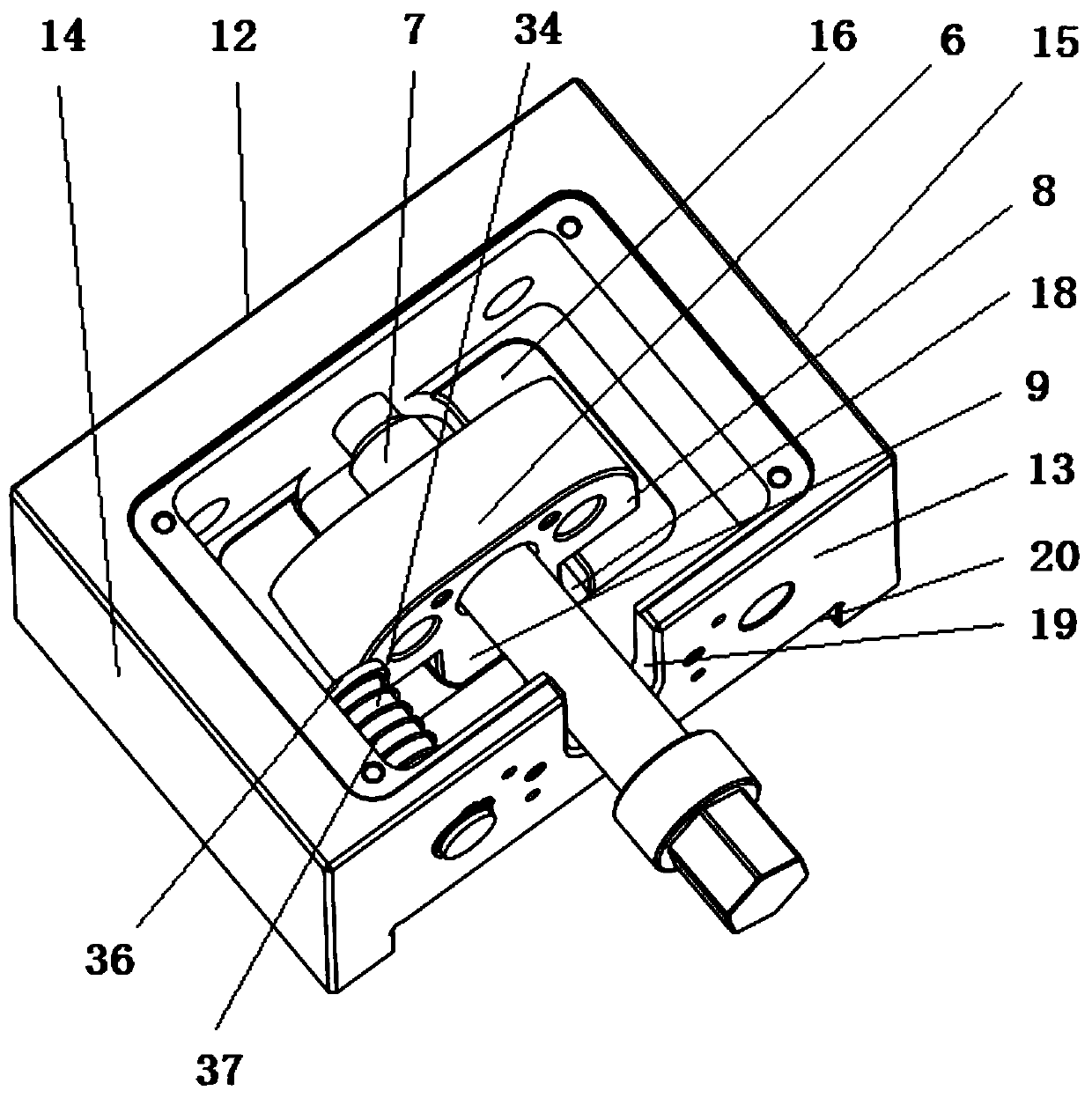
A kind of flat-nose pliers, fast technology, applied in the direction of clamping, supporting, positioning device, etc., can solve the problem of false clamping of workpiece, damage to workpiece and knife, take up large space, etc., to ensure smooth movement, improve processing accuracy, guarantee The effect of flatness

Pending Publication Date: 2019-09-27
杜洪波
View PDF0 Cites 3 Cited by
  • Summary
  • Abstract
  • Description
  • Claims
  • Application Information

AI Technical Summary

Problems solved by technology

That is: the general structure of the existing flat-nose pliers for machines is that the clamping screw is threadedly connected with the clamping nut at the lower end of the movable jaw, and the clamping surface on the upper part of the movable jaw is driven to clamp the workpiece with the clamping surface of the fixed jaw. The substantive deficiency of this structure is: when clamping the workpiece, it is necessary to knock the workpiece so that the positioning datum of the workpiece coincides completely with the datum plane of the vise
However, the workpiece will still be "upturned" on the side of the movable jaw, which makes the clamping force very small; it cannot meet the needs of workpiece clamping, so that the precise positioning of the workpiece cannot be guaranteed, and the high precision of workpiece processing cannot be guaranteed.
[0004] The second is: due to the upturning of the jaws, false clamping of the workpiece is caused. Therefore, when these vise clamps are erected or sideways to clamp the workpiece, it is easy to cause a safety accident; and the existing viseres are not set upright or sideways. The positioning datum surface required for installation, so the range of use of flat-nose pliers is greatly limited
[0005] The third is that the rear part of the slide rail of some vise pliers is an unconnected opening structure. This structure makes the vise very easy to open and deform outward during long-term use, which in turn affects the use of the vise
[0006] The 4th, because the flat-nose pliers of existing structure can not stand sideways clamping workpiece processing, therefore, when workpiece needs side-standing clamping processing, all can't be clamped by workpiece completely, reason is that the flat-nose pliers of existing structure all can't be eliminated. The sixth degree of freedom for clamping the workpiece;
[0007] Fifth, it is very dangerous that the existing flat-nose pliers cannot stably clamp workpieces of certain sizes. This is also a situation that the operator does not want to encounter. Machine tools; According to our investigation and retrieval of quick pliers with various structures at home and abroad, there is no company that has a device on the flat pliers that can indicate the forward or backward adjustment range of the movable pliers in the current state. That is to say, there are such unsafe hidden dangers in the fast vise pliers of all structures at home and abroad at present, and the method to remove this unsafe hidden danger has long been a great desire of the entire clamping enterprise and users.
[0008] Sixth, users who have used flat-nose pliers know that in general, when installing flat-nose pliers, it is necessary to use several pressure plates, compression screws and trapezoidal nuts to complete the fixation. This installation method takes up a lot of space. It is difficult to install multiple vise pliers on the same workbench or install vise pliers on a narrow workbench. This requires us to consider redesigning a structure with a smaller size, preferably even the pressure plate. The omitted structure of the flat-nose pliers meets the safe use of the flat-nose pliers in various installation methods

Method used


Image

  • Quick clamping flat tongs
  • Quick clamping flat tongs
  • Quick clamping flat tongs

Examples


Embodiment 1

[0082] Embodiment 1: In the process of clamping square workpieces in the present invention, when workpieces of different specifications need to be clamped and the distance between the movable jaw and the fixed jaw needs to be adjusted at a large distance, the operator holds the handle section at one end of the clamping screw , lift the clamping screw, so that the clamping screw drives the hook pin to leave the slot, and then push the movable jaw, the movable jaw quickly moves to the side of the workpiece along the slide rail, and pushes the workpiece through the clamping surface of the movable jaw Lean against the clamping surface of the fixed jaw, then press down and release the clamping screw, the clamping nut rotates smoothly with the arc surface of the bottom surface of the support arm in contact with the horizontal bottom surface, so that the clamping screw is reset on the screw Under the action of the device, it returns to the movable channel of the screw. At the same tim...

Embodiment 2

[0083] Embodiment 2: When using the flat-nose pliers to clamp the workpiece upright on the machine tool, the front end of the fixed jaw of the flat-nose pliers can be used as the positioning reference plane and quickly positioned by the spacer, and then the base is fixed on the vertical surface of the workbench. When clamping the workpiece, the operator holds the handle section at one end of the clamping screw, and lifts the clamping screw outward, so that the clamping screw drives the hook pin to leave the slot, and then under the action of gravity of the movable jaw, along the The slide rail quickly moves to the side of the workpiece, so that the movable jaw pushes the workpiece against the clamping surface of the fixed jaw and the movable jaw, and then pushes the clamping screw into the movable channel of the screw, and the hook pin is on the tension spring Under the action of the screw, it tightly leans against the card slot. At the same time, the clamping screw is reset to...

Embodiment 3

[0084] Embodiment 3: When the workpiece is clamped on the machine tool side by using the vise pliers, the support column can be fixed on the side wall of the slide rail through the connecting screw according to the need, and the outer end surface of the fixed support column and the side of the base are in the On the same positioning reference plane, if it is necessary to increase the adsorption area between the vise and the magnetic template of the workbench during side installation, the support column can be changed into a support pad and fixed on the side wall of the slide rail to ensure that the vise can stand sideways safely and stably. The surface is used as a positioning and ready to be adsorbed on the magnetic template; then, use a tool to penetrate the hole through the tool to screw the screw into the front to hide the through hole and then connect it with the vertical surface of the worktable, and then use the screw to screw in and hide the through hole It is fixedly t...


PUM


Abstract

The invention discloses high-quality quick clamping flat tongs. The high-quality quick clamping flat tongs are specially developed and designed for machinery manufacturing users and have the advantages that time and labor are saved in the operation process, and the safety is extremely high. The high-quality quick clamping flat tongs are quick clamping flat tongs of a brand new structure, and the quick clamping flat tongs of a brand new structure are researched and developed through many years after comprehensive retrieval and analysis processing is conducted on the whole market of existing flat tongs at home and abroad. The horizontal bottom face of a movable jaw is closely attached to the upper end face of a sliding rail under the action of a clamping nut and a screw reset device, the front end of a clamping screw abuts against the upper portion of the front clamping face of the movable jaw, the defect that a workpiece is warped on the movable jaw side is avoided, and then precise positioning and the machining high precision of the workpiece are guaranteed. The problem that existing quick clamping flat tongs have very serious potential safety hazards is thoroughly solved through the unique structure. The high-quality quick clamping flat tongs achieve a leading level in the world on the aspects of safely using and efficiently, quickly and conveniently clamping the workpiece.

Description

technical field [0001] The invention relates to the technical field of machine-used flat-nose pliers, in particular to a quick-clamping flat-nose pliers. Background technique [0002] Flat nose pliers are a general fixture in the field of mechanical processing, which is used to clamp workpieces for cutting. It is a random accessory for milling machines, drilling machines or CNC machine tools. Usually, the most commonly used flat-nose pliers on the market include parts such as a base, a bracket, a nut, a fixed jaw, a movable jaw, a slide rail, and a wire cylinder, and two parallel support frames are fixed on the upper end of the base. The upper end of the support frame is fixed with a slide rail, and a screw is provided between the support frames. One end of the slide rail is vertically fixedly connected to the fixed jaw, and the movable jaw is slidably connected to the slide rail, and a nut is fixed at the lower end of the movable jaw. After the screw is screwed to the nut,...

Claims


Application Information

Patent Timeline
Patent Type & Authority Applications(China)
IPC IPC(8): B23Q3/06
CPCB23Q3/066
Inventor 杜洪波
Owner 杜洪波
Learn More