Horizontal flying method of flying saucer and wing ring aircraft

A technology of wing-ring aircraft and wing-ring, which is applied in the field of wing-ring aircraft, can solve the problems that the central cabin cannot be set at the same time, and the communication connection between the cabins cannot be realized.

Pending Publication Date: 2019-09-27
郑小燕
View PDF18 Cites 3 Cited by
  • Summary
  • Abstract
  • Description
  • Claims
  • Application Information

AI Technical Summary

Problems solved by technology

[0004] Figures 47-50 of the accompanying drawings of the application also show that the existing wing-ring flying saucer technology cannot simultaneously arrange a central cabin (as shown in Figures 47-48) and an outer ring cabin (as shown in Figures 49-52), let alone realize two kinds of cabins. communication

Method used


Image

  • Horizontal flying method of flying saucer and wing ring aircraft
  • Horizontal flying method of flying saucer and wing ring aircraft
  • Horizontal flying method of flying saucer and wing ring aircraft

Examples


example 1

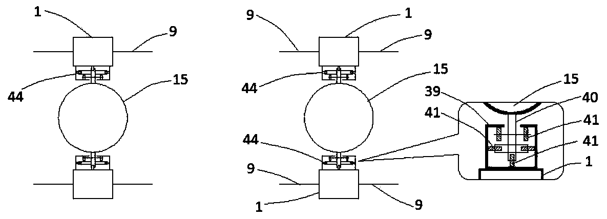
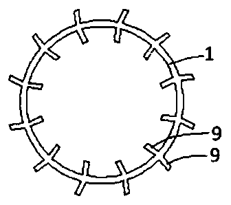
[0096] A wing ring flying saucer consisting of two figure 2 Shown wing ring and an annular nacelle 15 are connected to form, and concrete connection mode is as figure 1 Shown (two wing rings, two rail coupling rings 44 and an annular engine room 15 have constituted a disc-shaped wing ring machine, and the annular engine room 15 realizes dynamic motion by two vehicle rail coupling rings 44 and two wing rings 9 up and down. connect).

[0097] In this example, the rotation directions of the two wing rings are opposite, and the airfoil 9 has a lift airfoil shape, and the air pressure on the upward side of the airfoil is lower than that on the downward side when the air is cut.

[0098]The engine in this example can be an electric motor or an internal combustion engine. Engine can be installed in the appropriate position of annular vehicle frame (vehicle frame ring) 40, and the wheel 41 of engine and rail car is done dynamic connection, rotates with engine driven wheel 41, driv...

example 2

[0115] On the basis of Example 1, two groups of symmetrical signal transmitters are added in the Y1 orientation and Y2 orientation of the ring-shaped engine room 15, and the setting method is exactly the same as the two groups in the X1 orientation and X2 orientation, except that the orientation is different (see in Figure 4 ). When you only need to go forward, you only need to turn on X1 and X2, and you only need to turn on Y1 and Y2 when you need to turn.

example 3

[0117] On the basis of Example 1 or Example 2, the four signal transmitters a, A, q, and Q in the Y1 and Y2 directions, which can only transmit forward or reverse signals, can be changed to transmit forward signals. It is also a transmitter that can emit a reverse signal, and use the flying saucer direction joystick as its forward / reverse signal reverse controller. When the joystick is in a vertical state, a, A, q, and Q should stop sending any signals, so that the wings do not deflect when passing through the two directions of Y1 and Y2; when the joystick is pulled to the left, the left turn circuit should be connected, so that The signals sent by a, A, q, and Q cause the low-pressure surface of the wing to lean to the left of the original forward direction (such as Figure 8 ); when the joystick is pulled to the right, the right turn circuit should be connected, so that the signals sent by a, A, q, and Q cause the low-pressure surface of the vanes to lean to the right side o...


PUM


Abstract

A wing ring aircraft of which the maximum lift force is up to tens of thousands of tons is an optimal lift force device of a saucer-shaped aircraft. An existing wing ring aircraft technology can only gain horizontal driving power through an additionally-arranged engine, and the effective loading capacity is inevitably extremely reduced and energy consumption and pollution are increased by the additionally-arranged engine. With the adoption of the method, a flying saucer can be driven to march, turn, brake and fly without the additionally-arranged engine. The technical scheme is that wing sheets of wing rings or a fluid generator repeats the same deflection process while passing through the special route each time during two or more than three times of continuous circumferential movement. According to the horizontal flying method of the flying saucer and the wing ring aircraft, through arrangement of a parasite aircraft release manipulator or / and a parasite aircraft retracting manipulator, thus the cargo collecting and distribution speed of logistics and an express flying saucer can be greatly increased, and the cost can be decreased; a plurality of cabins are connected through radial channels, so that the effective loading space of the flying saucer is greatly increased; the lift force loss and strength reduction caused by space velocity difference of wing sections with different radius of a big wing ring aircraft can be solved; and the lift force and the mechanical strength of the flying saucer can be increased.

Description

technical field [0001] The invention relates to the technology of a wing ring aircraft, in particular to the technology of a disc-shaped aircraft using the wing ring aircraft as a lift device. Background technique [0002] Wing ring machine involves ring rotorcraft, ring wind turbine, ring water turbine and ring propeller machine, while wing ring flying saucer is a disc-shaped aircraft with wing ring machine as lifting device. [0003] Luo Conggui's "Wing Ring and Device and Method with Wing Ring" (publication number CN103195662A) more comprehensively records the wing ring machine technology. Although the description of this application relates to the deflection device of the engine and the blades, it does not involve and imply the deflection mode and technical effect described in the application at all, and Fig. 47 and Fig. 48 of the accompanying drawings of the description show that: the existing wing ring flying saucer The driving force in the horizontal direction can ...

Claims


Application Information

Patent Timeline
Patent Type & Authority Applications(China)
IPC IPC(8): B64C39/06
CPCB64C39/062B64C39/06B64C39/005B64C27/20B64C39/001B64C29/02
Inventor 罗琮贵
Owner 郑小燕
Why Eureka
Try Eureka