A multi-angle ultrasonic image fusion method, system and electronic equipment

An ultrasound image and fusion method technology, applied in the field of medical image processing, can solve the problems that the preoperative data cannot accurately represent the actual condition of the patient's diseased tissue, the lack of perception of the operating robot's surgical scene, and the high hardware cost, so as to improve the success rate of surgery and improve the Perception, Accurate Diagnosis and Outcomes of Surgery

Active Publication Date: 2021-08-24
SHENZHEN INST OF ADVANCED TECH CHINESE ACAD OF SCI
View PDF6 Cites 0 Cited by
  • Summary
  • Abstract
  • Description
  • Claims
  • Application Information

AI Technical Summary

Problems solved by technology

At present, LARN is mainly divided into three types based on preoperative data, intraoperative data and robot assistance. Among them, the method based on preoperative data means that the navigation data comes from preoperative CT or MRI and is displayed in the form of video fusion. The preoperative data obtained by the method cannot accurately represent the actual situation of the patient's diseased tissue during the operation; the method based on the intraoperative data refers to the use of a hybrid operating room to obtain intraoperative CT or MRI and display it in the form of video fusion. The system is too expensive and interfered by electronic equipment and even surgical instruments; the method based on robot assistance refers to the combination of surgical robot and LARN technology, but the hardware cost of this technology is very high, and there is still a lack of surgical scene awareness for operating robots (force feedback, depth information, etc.), and doctors also need professional training before they can use it

Method used


Image

  • A multi-angle ultrasonic image fusion method, system and electronic equipment
  • A multi-angle ultrasonic image fusion method, system and electronic equipment
  • A multi-angle ultrasonic image fusion method, system and electronic equipment

Examples


Embodiment Construction

[0073] In order to make the purpose, technical solution and advantages of the present application clearer, the present application will be further described in detail below in conjunction with the accompanying drawings and embodiments. It should be understood that the specific embodiments described here are only used to explain the present application, not to limit the present application.

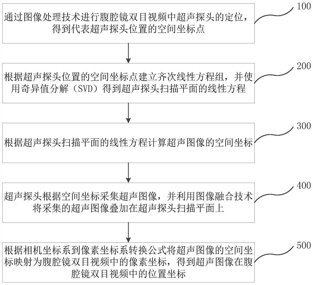
[0074] see figure 1 , is a flow chart of the multi-angle ultrasound image fusion method according to the embodiment of the present application. The multi-angle ultrasonic image fusion method of the embodiment of the present application includes the following steps:

[0075] Step 100: Positioning the ultrasonic probe in the binocular video of the laparoscope by image processing technology to obtain the spatial coordinate point representing the position of the ultrasonic probe;

[0076] In step 100, the ultrasonic probe positioning method is specifically as follows: firstly, the laparoscop...


PUM


Abstract

The present application relates to a multi-angle ultrasonic image fusion method, system and electronic equipment. Including: step a: positioning the ultrasonic probe through image processing technology, and using the conversion formula between camera coordinates and image pixel coordinates to obtain the spatial coordinate points of the ultrasonic probe in the laparoscopic binocular video; step b: according to the ultrasonic The spatial coordinate points of the probe establish homogeneous linear equations, and use singular value decomposition to obtain the linear equation of the scanning plane of the ultrasonic probe; step c: calculate the spatial coordinates of the ultrasonic image according to the linear equation of the scanning plane of the ultrasonic probe; step d : The ultrasonic probe collects ultrasonic images, and converts the spatial coordinates into corresponding pixel coordinates fused into the video image according to the conversion formula of camera coordinates and pixel coordinates, and completes the fusion of ultrasonic images into video images. The application can improve the doctor's ability to perceive the intraoperative environment, reduce the intraoperative risk, and improve the success rate of the operation.

Description

technical field [0001] The present application belongs to the technical field of medical image processing, and in particular relates to a multi-angle ultrasonic image fusion method, system and electronic equipment. Background technique [0002] Ultrasound images use ultrasonic beams to scan the human body, and obtain images of internal organs by receiving and processing reflected signals. They are often used to judge the location, size, and shape of organs, and determine the scope and physical properties of lesions. [0003] As a newly developed minimally invasive method, laparoscopic surgery is favored by patients due to its advantages of small postoperative scar, light pain, quick recovery, and short hospital stay, and has become the best choice for more and more patients. However, due to the limitation of the field of view and the poor perception of the intraoperative environment by doctors in laparoscopic surgery, many problems such as intraoperative bleeding, inaccurate...

Claims


Application Information

Patent Timeline
Patent Type & Authority Patents(China)
IPC IPC(8): G06T7/70G06T7/13G06T5/50G06K9/62G06F17/16G06F17/12A61B34/20A61B8/12A61B8/00
CPCG06T7/13G06T7/70G06T5/50G06F17/12G06F17/16A61B8/12A61B8/4245A61B34/20G06T2207/10081G06T2207/10088A61B2034/2065G06F18/23213
Inventor 熊璟方治屿夏泽洋
Owner SHENZHEN INST OF ADVANCED TECH CHINESE ACAD OF SCI
Why Eureka
Try Eureka