A water-cooled display module

A display module, water cooling and heat dissipation technology, applied in cooling/ventilation/heating transformation, photovoltaic modules, photovoltaic module support structures, etc. The panel works stably, the inefficiency of air transmission and heat dissipation, etc., to improve the charging efficiency, increase the sunlight exposure area, and save space.

Active Publication Date: 2021-02-19
XIAMEN TIANMA MICRO ELECTRONICS
View PDF6 Cites 0 Cited by
  • Summary
  • Abstract
  • Description
  • Claims
  • Application Information

AI Technical Summary

Problems solved by technology

[0002] With the vigorous development of the automobile industry, the requirements for the brightness of vehicle display products are getting higher and higher, which makes the number and power consumption of LEDs in vehicle backlights continue to increase, resulting in a sharp rise in the temperature of the backlight; and the photoelectric conversion rate of LEDs is relatively low. Low, a large amount of electric energy will be converted into heat energy during work. If the heat cannot be dissipated in time, the temperature of the LED chip will be too high, which will affect the service life, luminous efficiency and stability of the LED; at the same time, too high temperature will also make the liquid crystal The electro-optical performance of the display panel changes, affecting the use of the entire product
In the prior art, the heat of the backlight is generally transferred to the air, and the heat is taken away by the air for heat dissipation, but the efficiency of air transmission and heat dissipation is low, and the stable operation of the backlight and the display panel cannot be guaranteed.

Method used


Image

  • A water-cooled display module
  • A water-cooled display module
  • A water-cooled display module

Examples


Embodiment 1

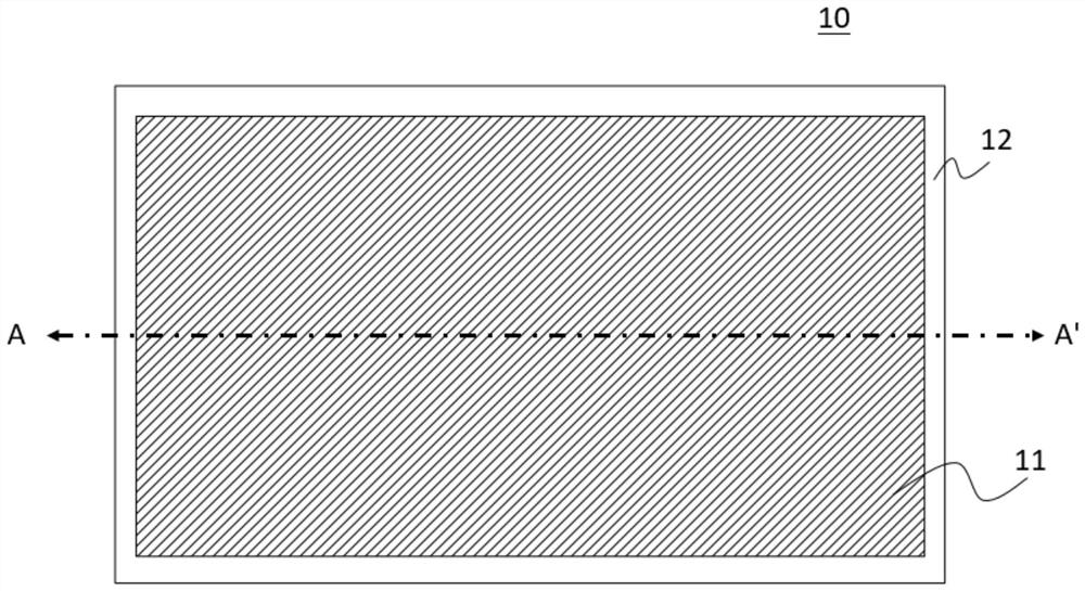
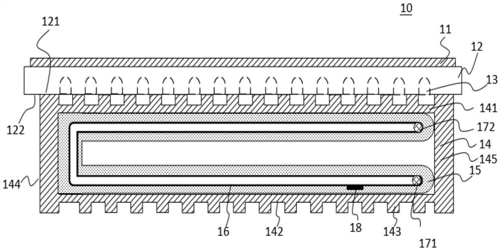
[0034] Please refer to figure 1 and figure 2 , figure 1 A top view of a water-cooled and heat-dissipating display module provided for the implementation of the present invention, figure 2 for along figure 1 In the schematic diagram of the AA' section in the middle, the water-cooled and heat-dissipating display module 10 includes a display panel 11 and a lamp board 12. The top surface 121 of the lamp board 12 close to the display panel 11 is provided with a plurality of LED lamp beads 13, and the lamp board 12 is far away from the display panel. The bottom 122 on one side of the panel 11 is provided with a cooling cavity 14 . A cooling water belt 15 is arranged inside the heat dissipation cavity 14 , and the cooling water belt 15 is arranged along the inner surface of the heat dissipation cavity 14 . As shown in the figure, the shape of the lamp panel 12 is a straight plate, and the heat dissipation cavity 14 includes a top surface 141 near the bottom 122 of the lamp pane...

Embodiment 2

[0047] Figure 6 A schematic diagram of a water-cooled and heat-dissipating display module provided in Embodiment 2 of the present invention. The water-cooling and heat-dissipating display module 20 includes a display panel 21 and a lamp panel 22. The top surface 221 of the lamp panel 22 near the display panel 21 is provided with a plurality of The LED lamp bead 23 and the bottom 222 of the lamp board 22 away from the display panel 21 are provided with a cooling cavity 24 . A cooling water belt 25 is arranged inside the heat dissipation cavity 24 , and the cooling water belt 25 is arranged along the inner surface of the heat dissipation cavity 24 . As shown in the figure, the cooling water belt 25 is a U-shaped structure, and the cooling water belt 25 of the U-shaped structure is in contact with the top surface 241, the bottom surface 242, and a side surface 244 between the top surface 241 and the bottom surface 242 of the cooling cavity 24, On the other side is the opening p...


PUM


Abstract

An embodiment of the present invention provides a water-cooled and heat-dissipating display module. The display module includes a display panel and a lamp board. A plurality of LED beads are arranged on the top surface of the lamp board near the display panel. A cooling cavity is provided at the bottom of the lamp board away from the display panel; a cooling water belt is arranged in the cooling cavity, and the cooling water belt is arranged along the inner surface of the cooling cavity. The display module provided by the present invention can increase the heat dissipation rate by arranging cooling water belts in the heat dissipation cavity, ensure that the working temperature of the lamp panel is normal, and will not cause excessive temperature, thereby ensuring the luminous efficiency and stable operation of the LED lamp bead The normality of sex and service life. In addition, because the heat generated by the light board is absorbed in time, it can also ensure the stable operation of the display panel.

Description

【Technical field】 [0001] The invention relates to the field of display technology, in particular to a water-cooled and heat-dissipating display module. 【Background technique】 [0002] With the vigorous development of the automobile industry, the requirements for the brightness of vehicle-mounted display products are getting higher and higher, which makes the number and power consumption of LEDs in vehicle-mounted backlights continue to increase, resulting in a sharp rise in the temperature of the backlight; and the photoelectric conversion rate of LEDs is relatively low. Low, a large amount of electric energy will be converted into heat energy during work. If the heat cannot be dissipated in time, the temperature of the LED chip will be too high, which will affect the service life, luminous efficiency and stability of the LED; at the same time, too high temperature will also make the liquid crystal The electro-optical performance of the display panel changes, affecting the u...

Claims


Application Information

Patent Timeline
Patent Type & Authority Patents(China)
IPC IPC(8): H05K7/20H02J7/35H02S20/30
CPCH02J7/35H05K7/20272H05K7/20281H05K7/20981H02S20/30Y02E10/50
Inventor 刘远明
Owner XIAMEN TIANMA MICRO ELECTRONICS
Why Eureka
Try Eureka