
Production equipment and production process of steelmaking converter flue

A steelmaking converter and production process technology, applied to other manufacturing equipment/tools, manufacturing tools, etc., can solve the problems of wasting working time, inability to adjust the size, and time-consuming manual operation, so as to save labor and working time and improve product quality , The effect of improving work efficiency

Inactive Publication Date: 2019-10-01
WUXI XIANGLONG GLOBAL TECH CO LTD
View PDF0 Cites 2 Cited by
  • Summary
  • Abstract
  • Description
  • Claims
  • Application Information

AI Technical Summary

Problems solved by technology

When punching the inner wall of the annular pipe, it is necessary to manually rotate the annular pipe to each position that needs to be punched, and then use a punching machine to align the holes at the position, which consumes manpower, and workers are likely to cause work-related injuries during the operation. Operation is time-consuming and inefficient
[0004] A large flue needs to use a large number of steel pipes, and the connection between straight pipes requires the use of bent pipes. In traditional pipe bending equipment, the radius of rotation of the bent pipe remains unchanged, that is, only the length of the bent pipe can be changed, but The arc is fixed, and when it is necessary to use elbows with different arcs, this equipment cannot meet the requirements; in traditional pipe bending equipment, the cylindrical hole of the chuck mechanism that clamps the end of the elbow cannot be adjusted in size, so only It can adapt to steel pipes of the same thickness. When the thickness of the steel pipes is different, the collet mechanism in the pipe bending equipment needs to be replaced, thus wasting working time

Method used


Image

  • Production equipment and production process of steelmaking converter flue
  • Production equipment and production process of steelmaking converter flue
  • Production equipment and production process of steelmaking converter flue

Examples


Embodiment Construction

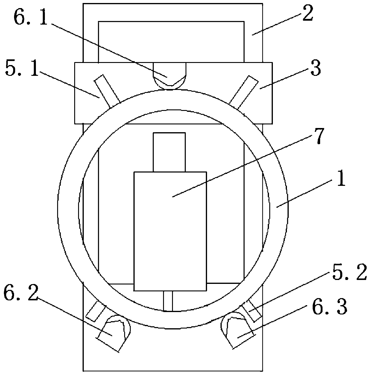
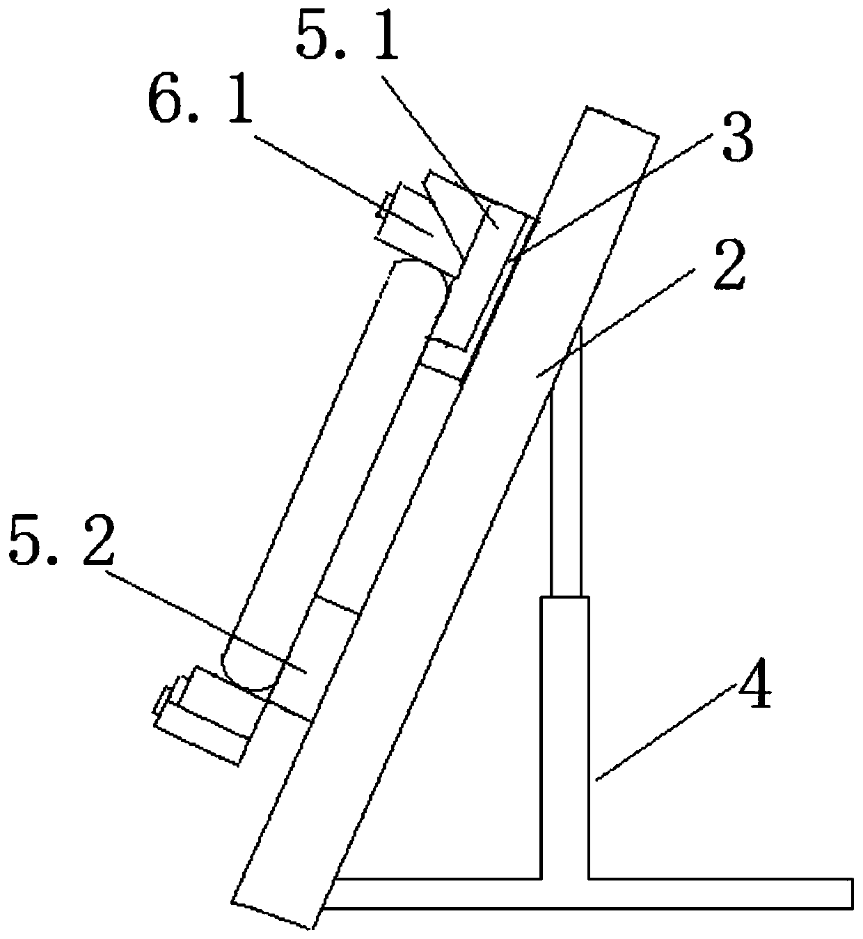
[0036] see Figure 1 to Figure 8 , the present invention relates to the production equipment and production process of the steelmaking converter flue. The process steps of the production process are: firstly, cutting the flue; The pipe equipment bends the end of the steel pipe to form an elbow; then welds between straight pipes and between straight pipes and elbows. The annular pipe is welded outside the pipeline, and the through hole on the inner wall of the annular pipe communicates with the inside of the pipeline. ; After the welding is completed, the welding port is polished; after the flue is hoisted in place, it is then welded as a whole; after the welding is completed, the flue is heat treated; after the heat treatment is completed, the flue is painted; The inner wall is polished and anti-corrosion.

[0037] The production equipment used in the above production process includes a punching device for a flue annular pipe and a pipe bending device.

[0038] The punching ...


PUM


Abstract

The invention relates to production equipment and production process of a steelmaking converter flue. The production process comprises the following steps: at first, blanking and cutting a flue; then,using a flue annular pipe perforating device to perforate an annular pipe, and using pipe bending equipment to bend the end part of a steel pipe to form an elbow pipe; welding straight pipes, weldinga straight pipe and the elbow pipe, and welding the annular pipe at the external part of a pipeline in the mode that a through hole in the inner wall of the annular pipe communicates with the interior of the pipeline; after welding, polishing a weld bore; after hoisting the flue in place, integrally welding the flue; after welding, carrying out thermal treatment on the flue; after the thermal treatment, spraying paint on the flue; and finally, after the flue is mounted, carrying out polishing and anticorrosion treatment on the inner wall of the flue. The invention relates to the production equipment and the production process of the steelmaking converter flue to form an integrated technological process, and all working procedures are cooperated tightly to ensure the production efficiencyand the working quality.

Description

technical field [0001] The invention relates to production equipment and a production process for steelmaking converter flue. Background technique [0002] The flue is a tubular device for exhaust gas and smoke discharge. The quality of the flue plays a vital role in the effective discharge of smoke and waste gas. It is self-evident for the smoke emission of steelmaking converter equipment. [0003] The annular pipe is an important part of the flue, and the inner wall of the annular pipe needs to be drilled manually to match the main body of the flue. When punching the inner wall of the annular pipe, it is necessary to manually rotate the annular pipe to each position that needs to be punched, and then use a punching machine to align the holes at the position, which consumes manpower, and workers are likely to cause work-related injuries during the operation. The operation is time-consuming and inefficient. [0004] A large flue needs to use a large number of steel pipes, ...

Claims


Application Information

Patent Timeline
IPC IPC(8): B23P15/00B23P23/04
CPCB23P15/00B23P23/04
Inventor 邓伟赵志龙赵勇龙赵杨
Owner WUXI XIANGLONG GLOBAL TECH CO LTD
Learn More