Eureka AIR delivers breakthrough ideas for toughest innovation challenges, trusted by R&D personnel around the world.

Drum brake pad abrasion line processing equipment

A technology for processing equipment and brake pads, which is applied in the field of brake pad processing equipment, can solve the problems of manpower consumption and low processing efficiency, and achieve the effects of saving labor, reducing labor costs, and increasing the contact area

Pending Publication Date: 2019-10-01
山东梁山耐驰汽车零部件有限公司
View PDF0 Cites 2 Cited by
  • Summary
  • Abstract
  • Description
  • Claims
  • Application Information

AI Technical Summary

Problems solved by technology

[0003] The brake pads used on semi-trailers are called drum brake pads. The brake pads of this type of vehicles wear out quickly. In order to ensure driving safety, the brake pads need to be replaced regularly. In order to facilitate the inspection of the brake pads, during production During the processing, the wear line will be processed on the edge of the brake pad to remind the use status of the brake pad. The processing of the wear line is mainly to grind a groove on the end of the brake pad through the grinding wheel. The edge of the groove is worn The limit is the wear line. The existing processing equipment is to manually fix the brake pads on the turntable for grinding. It is necessary to manually place the unpolished brake pads and remove the polished brake pads. The entire processing process is very labor-intensive, and Processing efficiency is low

Method used


Image

  • Drum brake pad abrasion line processing equipment
  • Drum brake pad abrasion line processing equipment
  • Drum brake pad abrasion line processing equipment

Examples


Embodiment Construction

[0037] The following will clearly and completely describe the technical solutions in the embodiments of the present invention with reference to the accompanying drawings in the embodiments of the present invention. Obviously, the described embodiments are only some, not all, embodiments of the present invention. Based on the embodiments of the present invention, all other embodiments obtained by persons of ordinary skill in the art without making creative efforts belong to the protection scope of the present invention.

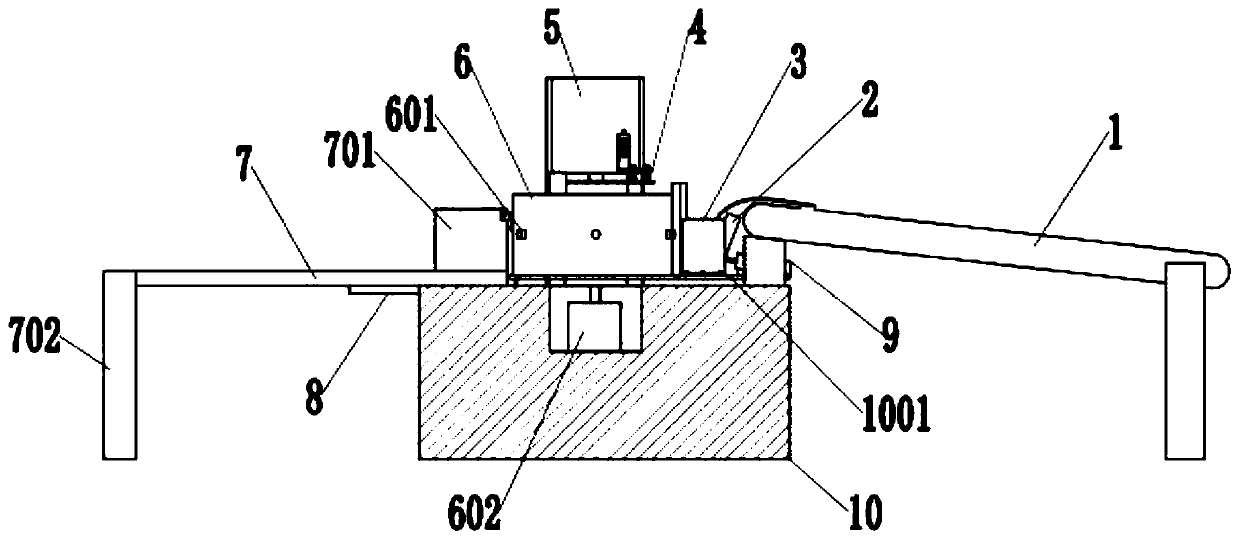
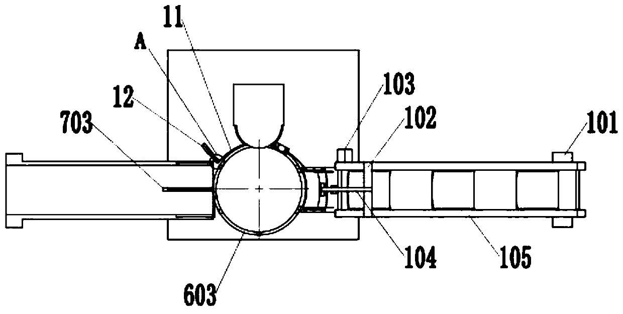
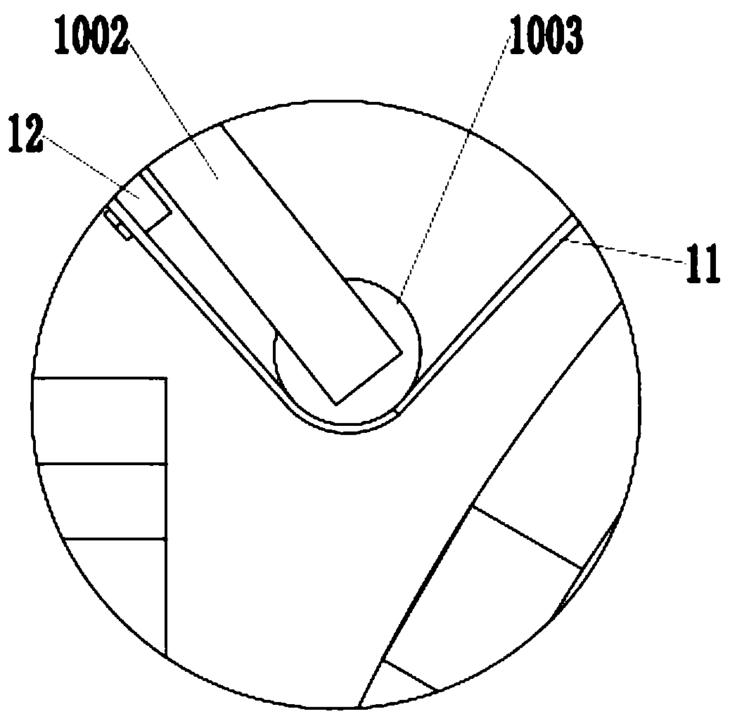
[0038] Such as figure 1 , 2, 4, and 5, a processing equipment for a drum brake pad wear line, including a feed conveyor belt 1, a tablet pressing device 4, a grinder 5, a turntable 6, a discharge slide 7, a workbench 10, and on the workbench 10 A grinder 5 and a turntable 6 are provided, and the turntable 6 is arranged close to the grinder 5, and the side wall of the turntable 6 is evenly provided with a material shifting protrusion 601, and there are at leas...


PUM


Abstract

The invention discloses drum brake pad abrasion line processing equipment which comprises a feeding conveyor belt, a tableting device, a grinding machine, a rotating table, a discharging sliding plateand a workbench, wherein the grinding machine and the rotating table are arranged on the workbench; the rotating table is arranged close to the grinding machine; dialing bulges are uniformly arrangedon the side wall of the rotating table; a rotating motor connected with the rotating table is arranged in the workbench; the feeding conveyor belt and the discharging sliding plate are correspondingly arranged on two sides of the rotating table; a bracket is arranged between the feeding conveyor belt and the rotating table; first baffle plates are arranged on two sides of the bracket; a second air cylinder used for pushing brake pads is arranged below the feeding conveyor belt; second baffle plates are arranged on two sides of the end, close to the rotating table, of the discharging sliding plate; pulling pieces are arranged between the first baffle plates and the second baffle plates, and positioned between the rotating table and the grinding machine; a dialing hole is formed in the discharging sliding plate; a first air cylinder is arranged below the discharging sliding plate; and a pulling block is arranged at the end part of the first air cylinder and matched with the dialing hole.

Description

technical field [0001] The invention relates to the technical field of brake pad processing equipment, in particular to a processing equipment for drum brake pad wear lines. Background technique [0002] Brake pads are also called brake pads. In the braking system of a car, the brake pads are the most critical safety parts. The brake pads play a decisive role in the quality of all braking effects, so good brake pads are the protectors of people and cars. [0003] The brake pads used on semi-trailers are called drum brake pads. The brake pads of this type of vehicles wear out quickly. In order to ensure driving safety, the brake pads need to be replaced regularly. In order to facilitate the inspection of the brake pads, during production During the processing, the wear line will be processed on the edge of the brake pad to remind the use status of the brake pad. The processing of the wear line is mainly to grind a groove on the end of the brake pad through the grinding wheel...

Claims


Application Information

Patent Timeline
Patent Type & Authority Applications(China)
IPC IPC(8): B24B19/28B24B19/02B24B41/00B24B41/06B24B55/00
CPCB24B19/28B24B19/02B24B41/005B24B41/06B24B55/00
Inventor 刘汉启
Owner 山东梁山耐驰汽车零部件有限公司
Why Eureka
Eureka Blog
Learn More