Simulation method for direct coupling of three loads of temperature, pressure and vibration on sensor

A simulation method and sensor technology, applied in the direction of instrumentation, calculation, electrical digital data processing, etc., can solve problems such as difficulty in exporting initial stress files, difficulty in obtaining initial stress files, sensor influence, etc., to overcome conflicts in boundary constraint settings, The maximum response result is accurate and the effect of overcoming stress accumulation

Active Publication Date: 2019-10-08
UNIV OF ELECTRONICS SCI & TECH OF CHINA
View PDF3 Cites 2 Cited by
  • Summary
  • Abstract
  • Description
  • Claims
  • Application Information

AI Technical Summary

Problems solved by technology

First of all, in the frequency domain simulation, only the coupling mode of prestressed mode and vibration can be adopted. The coupling mode of prestressed mode and vibration is the vibration simulation under the influence of temperature and pressure load, and only The vibration simulation results under the influence of temperature and pressure, in which temperature and pressure will affect the vibration results, but the simulation results of the joint action of temperature, pressure and vibration cannot be obtained; the coupling method of prestressed mode and vibration is adopted to To obtain the maximum response of vibration, it is impossible to obtain the stress-strain situation of the sensor under three stresses for a long time, and the coupling simulation method of mode and vibration can only get a rough result; secondly, in the simulation method of coupling mode and vibration There is a conflict between the boundary conditions of load application and the load application boundary conditions of temperature and pressure in the static simulation. In the sensor comprehensive stress simulation, the simulation of temperature and pressure adopts a fixed constraint method in the Z direction of the bottom surface of the sensor structure, which is different from the actual working environment. similar; for vibration simulation, a fixed constraint method is generally used, but it is difficult to simulate the actual boundary conditions of the sensor under environmental loads such as temperature, pressure, vibration, etc. by using a fixed constraint method on the bottom of the sensor; finally, a prestressed The coupling method of mode and vibration is difficult to derive the initial stress file, which is mainly used for indirect coupling with pressure and temperature in static simulation
At present, only the superposition of working conditions can be used to superimpose the results of the three stresses. The superposition of working conditions brings a large method error. This method is the superposition of various load simulation results and cannot reflect various loads. The result of mutual influence
According to the above analysis, it can be seen that the boundary constraints of the coupling mode of prestress mode and vibration, the indirect coupling of various environmental stresses lead to method errors, and how to derive the initial stress file in the frequency domain has become an urgent problem to be solved.
[0005] Convert the frequency domain signal into a time domain signal, convert the PSD power spectrum into a time domain signal of acceleration, and use transient simulation, which will solve the impact of long-term vibration on the sensor in a high temperature and high pressure environment, and the boundary of the sensor in different environments The conflict of constraints and the difficulty of obtaining the initial stress file under the maximum vibration response for frequency domain simulation under indirect coupling
However, at present, there are few studies on the direct coupling of high temperature, high pressure and vibration. Most of the research only discusses the simulation of prestressed modal and vibration coupling. There is almost no research on how to perform long-term coupling of temperature, pressure and vibration in the time domain. no mention

Method used


Image

  • Simulation method for direct coupling of three loads of temperature, pressure and vibration on sensor
  • Simulation method for direct coupling of three loads of temperature, pressure and vibration on sensor
  • Simulation method for direct coupling of three loads of temperature, pressure and vibration on sensor

Examples


Embodiment Construction

[0042] The technical solution of the present invention will be described in detail below with reference to the drawings and specific embodiments.

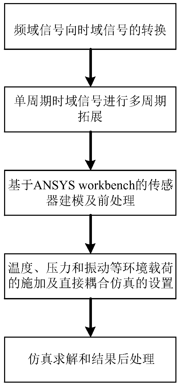
[0043] Such as figure 1 Shown is the overall flow diagram of the simulation method for the direct coupling of temperature, pressure, and vibration on the sensor proposed in the present invention, including the conversion of frequency domain signals to time domain signals, the expansion of time domain signals, the establishment of sensor models based on ANSYSworkbench and Pre-processing, three kinds of environmental load application and coupling simulation condition setting, simulation solution, post-processing and analysis of the results, etc., the coupling simulation of multiple loads is the comprehensive stress simulation, based on the three-load direct coupling simulation method proposed by the present invention The obtained comprehensive stress simulation of the sensor can realize the direct coupling simulation of various environme...


PUM


Abstract

The invention discloses a simulation method for directly coupling three loads of temperature, pressure and vibration on a sensor. The method comprises the following steps: firstly, converting a frequency domain signal of a vibration load into a time domain signal, and expanding to obtain a long-time time time domain signal; adopting ANSYS work bench software to model the sensor, and completing pretreatment; performing simulation setting of direct coupling; wherein the simulation solving step length is 2; in the first solving step, applying a pressure load and a temperature load to the sensor;in the second solving step, enabling a long-time time domain signal to serve as a vibration load to be applied to the sensor, performing direct coupling simulation of the three loads to obtain stressdistribution of the whole structure of the sensor within the whole simulation time wherein the sub-step length of the second solving step is not larger than the minimum time length of change of the long-time time domain signal; and performing post-processing on the simulation result to obtain a simulation maximum value of the sensor under coupling of three loads. According to the simulation methodprovided by the invention, the problems of errors, boundary constraint conflicts and difficulty in exporting an initial stress file in frequency domain simulation of an indirect coupling simulation method are solved.

Description

Technical field [0001] The invention belongs to the technical analysis field of reliability of sensors in harsh environments, and relates to a comprehensive stress simulation method, in particular to a comprehensive stress simulation method in which high temperature, high pressure, and vibration are directly coupled on the sensor. Background technique [0002] Silicon carbide high temperature capacitive sensors have good advantages and are mainly used in complex and harsh environment fields such as automotive systems, industrial test control, environmental monitoring, and aero engine detection. The working process of this sensor is mainly in harsh and complex environments. The performance, cost and life of the product have a greater impact. [0003] The working environment of the sensor may have multiple environments such as high temperature, high pressure, and vibration at the same time, and it becomes extremely difficult to evaluate the reliability of the sensor through actual te...

Claims


Application Information

Patent Timeline
Patent Type & Authority Applications(China)
IPC IPC(8): G06F17/50
CPCG06F30/23
Inventor 杜江锋杨荣森鲁岩荣丽梅罗天成何金泽
Owner UNIV OF ELECTRONICS SCI & TECH OF CHINA
Why Eureka
Try Eureka