Nuclear reactor power source with heat pipes bidirectionally inserted into reactor core

A nuclear reactor and core technology, applied in the field of nuclear reactor power supply, can solve the problems of low output power, strict space restrictions, and difficult flexible deployment, etc., and achieve the effects of strong environmental adaptability, broad application prospects, and increased numbers

Inactive Publication Date: 2019-10-08
XI AN JIAOTONG UNIV
View PDF12 Cites 9 Cited by
  • Summary
  • Abstract
  • Description
  • Claims
  • Application Information

AI Technical Summary

Problems solved by technology

At present, the battery life of chemical power sources is very limited, and it is difficult for batteries and fuel cells to meet the needs of continuous use for several months or even years; internal combustion engines are supplemented by continuous fuel; Long lasting, but output power is too low
[0003] The heat pipe nuclear reactor power supply is one of the important candidates for flexible deployment, high power, and high endurance power supply. At present, the existing nuclear reactor power supply adopts the heat pipe cooling core, and the heat pipes are inserted from one side of the core. The space constraints are relatively strict, the number of thermoelectric conversion elements is usually small, and the output power and energy utilization of the power supply are low

Method used


Image

  • Nuclear reactor power source with heat pipes bidirectionally inserted into reactor core

Examples


Embodiment Construction

[0016] In order to better illustrate the present invention, the working principle of the present invention will now be described in conjunction with the accompanying drawings.

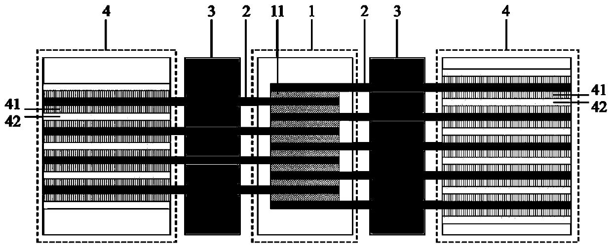
[0017] Such as figure 1 As shown, the layout diagram of the nuclear reactor power supply in which the heat pipes of the present invention are bidirectionally inserted into the core includes a core 1, two sets of heat pipes 2, shielding bodies 3 and two sets of power generation components 4, and one end of the two sets of heat pipes 2 is connected from the core 1 respectively. Both sides are inserted into the core 1, and the other end is respectively inserted into the power generation component 4. The shield 3 is arranged between the core 1 and the power generation component 4. The heat pipe 2 passes through the shield 3. The shield 3 protects the power generation component 4 from Radiation damage to core 1. The power generation component 4 adopts the silent temperature difference thermoelectric conver...


PUM


Abstract

The invention discloses a nuclear reactor power source with heat pipes bidirectionally inserted into a reactor core. The nuclear reactor power source comprises the reactor core, two groups of the heatpipes, two groups of shields and two groups of power generating parts. The two groups of the shields and the power generating parts are symmetrically arranged on two sides of the reactor core, one ends of the two groups of the heat pipes are inserted into the reactor core from two sides of the reactor core while the other ends are inserted into the two groups of the power generating parts respectively, the shields are arranged between the reactor core and the power generating parts, the heat pipes penetrate the shields, and the shields protect the power generating parts from radiation damagescaused by the reactor core. By adoption of a silent thermoelectric conversion technique, each power generating part comprises thermocouple conversion elements and cooling passages, wherein the thermocouple conversion elements and the cooling passages are arranged at intervals. One side of each thermocouple conversion element is heated by the corresponding heat pipe while the other side is cooledby a working medium in the corresponding cooling passage, so that temperature difference is formed on two sides of each thermocouple conversion element while thermoelectric potential is formed, and heat energy is converted into electric energy for multipurpose equipment and systems to use. By arrangement of the two groups of the power generating parts at two ends of the reactor core, the energy utilization rate is increased.

Description

technical field [0001] The invention relates to the technical field of nuclear reactor design, in particular to a nuclear reactor power supply in which heat pipes are bidirectionally inserted into the core. Background technique [0002] With the advancement of science and technology, a variety of complex-purpose equipment systems have put forward a major demand for flexible deployment and high-endurance power supplies. At present, the battery life of chemical power sources is very limited, and it is difficult for batteries and fuel cells to meet the needs of continuous use for several months or even years; internal combustion engines are supplemented by continuous fuel; Long lasting, but output power is too low. [0003] The heat pipe nuclear reactor power supply is one of the important candidates for flexible deployment, high power, and high endurance power supply. At present, the existing nuclear reactor power supply adopts the heat pipe cooling core, and the heat pipes a...

Claims


Application Information

Patent Timeline
Patent Type & Authority Applications(China)
IPC IPC(8): G21C15/06G21C15/14G21D7/04
CPCG21C15/06G21C15/14G21D7/04Y02E30/00Y02E30/30
Inventor 王成龙孙浩唐思邈田文喜苏光辉秋穗正
Owner XI AN JIAOTONG UNIV
Why Eureka
Try Eureka