
Image sensor and method for forming same

An image sensor and photoelectric sensing technology, which is applied in the field of semiconductors, can solve problems such as poor imaging quality of image sensors, aggravated pixel optical crosstalk and electrical crosstalk, unfavorable highlight overflow, etc., to reduce size, improve imaging quality, The effect of avoiding undesired effects

Inactive Publication Date: 2019-10-08
HUAIAN IMAGING DEVICE MFGR CORP
View PDF4 Cites 0 Cited by
  • Summary
  • Abstract
  • Description
  • Claims
  • Application Information

AI Technical Summary

Problems solved by technology

This will lead to many problems, for example, the light originally incident on a certain pixel unit may enter the adjacent pixel unit through the gap between the DTI structure and the corresponding STI structure, thereby causing serious light crosstalk (light crosstalk); another example, when When the incident light intensity is large and the number of photo-generated carriers is too large, the photo-generated carriers may overflow to adjacent pixel units, resulting in an unfavorable blooming effect.
These problems will aggravate the optical crosstalk and electrical crosstalk between pixels, resulting in poor imaging quality and other performance of the image sensor.

Method used


Image

  • Image sensor and method for forming same
  • Image sensor and method for forming same
  • Image sensor and method for forming same

Examples


Embodiment Construction

[0018] Various exemplary embodiments of the present disclosure will be described in detail below with reference to the accompanying drawings. It should be noted that relative arrangements of components and steps, numerical expressions and numerical values ​​set forth in these embodiments do not limit the scope of the present disclosure unless specifically stated otherwise.

[0019] The following description of at least one exemplary embodiment is merely illustrative in nature and in no way intended as any limitation of the disclosure, its application or uses. That is, the structures and methods herein are presented by way of example to illustrate various embodiments of the structures and methods of this disclosure. However, those skilled in the art will appreciate that they illustrate merely exemplary, and not exhaustive, ways in which the disclosure may be practiced. Furthermore, the figures are not necessarily to scale and some features may be exaggerated to show details of...


PUM


Abstract

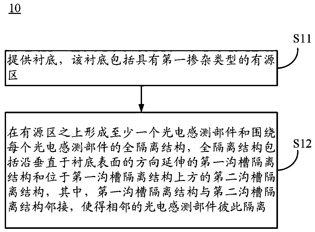
The present disclosure relates to an image sensor and a method for forming the same. The method for forming the image sensor comprises the steps of: providing a substrate including an active region ofa first doping type; forming, over the active region, at least one photoelectric sensing component and full isolation structures surrounding respective photoelectric sensing components, wherein eachfull isolation structure includes a first trench isolation structure extending in a direction perpendicular to the surface of the substrate and a second trench isolation structure over the first trench isolation structure, the first trench isolation structure is adjacent to the second trench isolation structure such that adjacent photoelectric sensing components are isolated from each other.

Description

technical field [0001] The present disclosure relates to the field of semiconductors, and in particular, to image sensors and methods of forming the same. Background technique [0002] An image sensor is a functional device capable of sensing radiation (eg, optical radiation, including but not limited to visible light, infrared rays, ultraviolet rays, etc.) and thereby generating corresponding electrical signals. Image sensors are widely used in various electronic products that need to sense radiation. [0003] An image sensor may include a plurality of pixel units, where each pixel unit has a photo-sensing component, such as a photodiode. The image sensor may include trench isolation structures disposed between adjacent pixel units for physical isolation, electrical isolation, and the like. For example, an image sensor may include a deep trench isolation (DTI) structure and / or a shallow trench isolation (STI) structure for isolating adjacent pixel units. [0004] Since i...

Claims


Application Information

Patent Timeline
Patent Type & Authority Applications(China)
IPC IPC(8): H01L27/146
CPCH01L27/1463H01L27/14683
Inventor 方明旭李春杰夏春秋
Owner HUAIAN IMAGING DEVICE MFGR CORP
Learn More