Wireless power supply system for locomotive rotating component monitoring device and monitoring device

A technology for rotating parts and wireless power supply, which is applied in the direction of circuit devices and electrical components, and can solve problems that affect the safety of locomotives, are less difficult to manufacture, and have complex structures.

Pending Publication Date: 2019-10-08
HANGZHOU ROUGU TECH CO LTD
View PDF0 Cites 0 Cited by
  • Summary
  • Abstract
  • Description
  • Claims
  • Application Information

AI Technical Summary

Problems solved by technology

The installation and transformation of the tested components by wireless energy supply is relatively small, the constraints of the installation structure are small, and the manufacturing difficulty is relatively small. Ordinary wireless energy supply based on the principle of electromagnetic induction can only work in a short distance. It is far away and suitable for magnetic resonance wireless energy supply, but the existing magnetic resonance wireless function method has complex structure, high cost, and is easy to cause interference to rotating parts, affecting the driving safety of locomotives

Method used


Image

  • Wireless power supply system for locomotive rotating component monitoring device and monitoring device
  • Wireless power supply system for locomotive rotating component monitoring device and monitoring device
  • Wireless power supply system for locomotive rotating component monitoring device and monitoring device

Examples


Embodiment Construction

[0025] In order to further explain the technical means and effects of the present invention to achieve the intended purpose of the invention, a detailed description is given below with reference to the accompanying drawings and preferred embodiments.

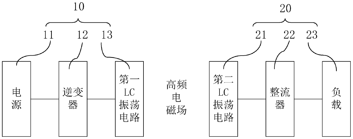
[0026] The present invention provides a wireless power supply system for a monitoring device of a locomotive rotating part and a monitoring device having the same. The wireless power supply system can realize a stable and reliable power supply for the monitoring device on the rotating part of a locomotive.

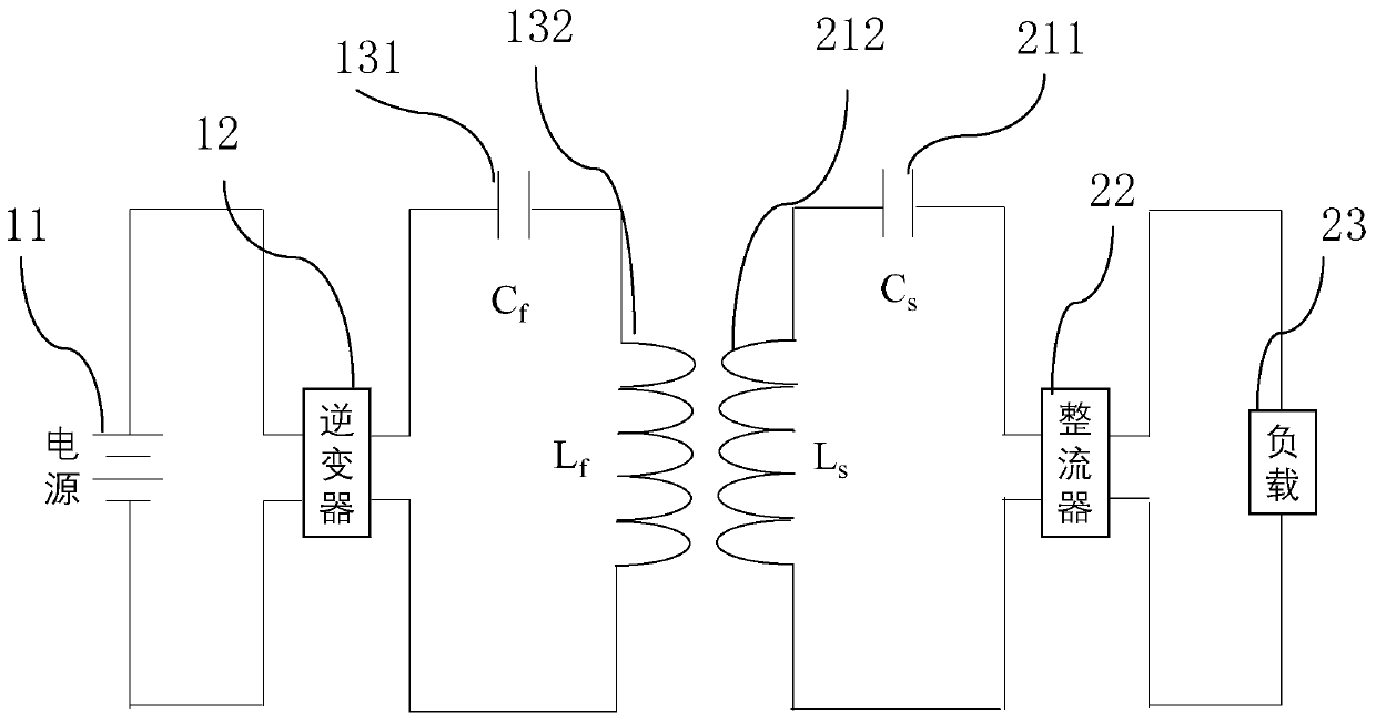
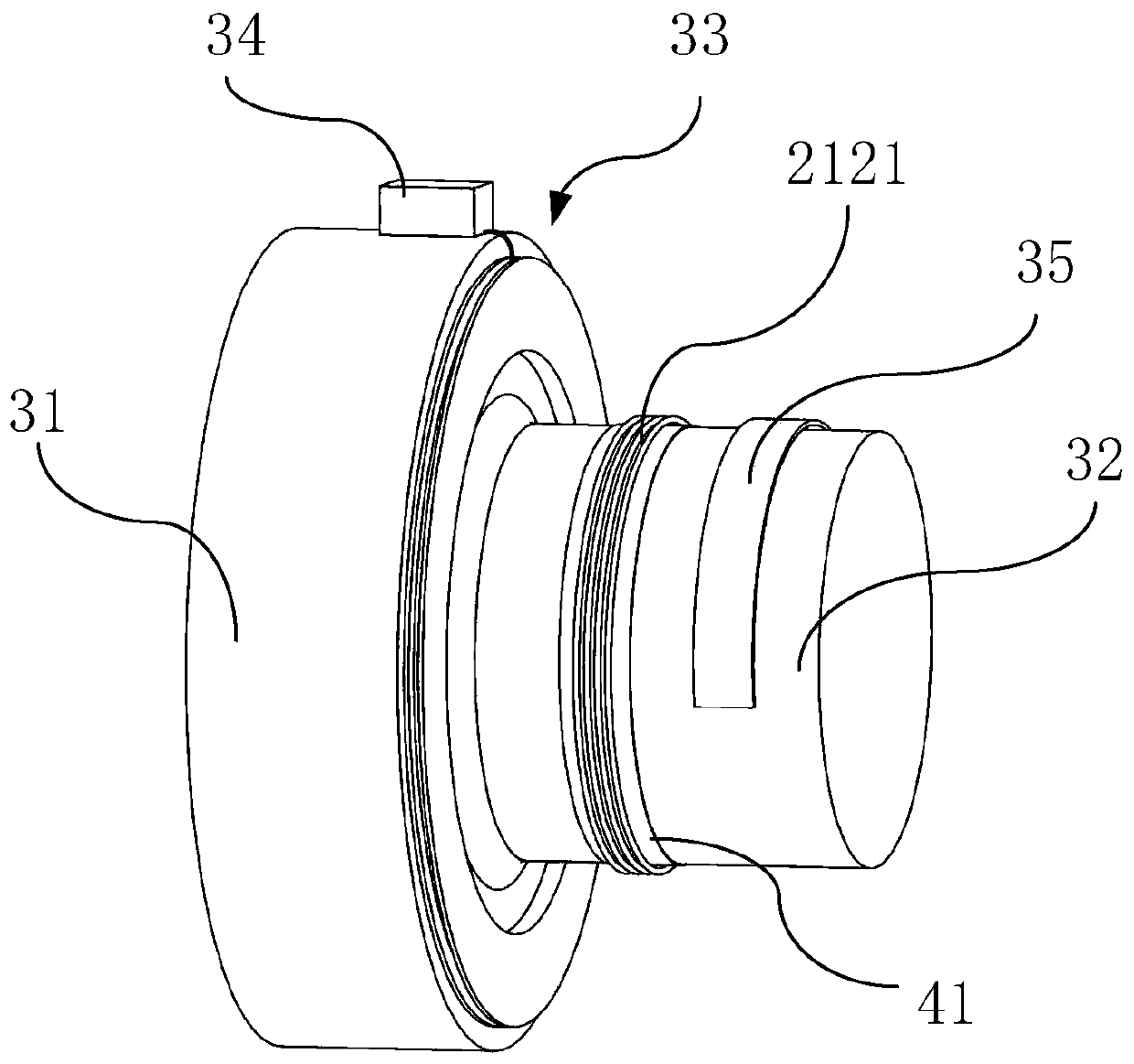
[0027] figure 1 Shown is a system block diagram of a wireless power supply system of a device for monitoring rotating parts of a locomotive provided by an embodiment of the present invention, figure 2 Shown as figure 1 Schematic diagram of the circuit structure of the wireless power supply system in China, image 3 Shown is a schematic front view of the structure of the wireless power supply system of the locomotive rotating compo...


PUM


Abstract

The invention provides a wireless power supply system for a locomotive rotating component monitoring device and the monitoring device. The wireless power supply system comprises an energy transmittingmodule and an energy receiving module. The energy transmitting module comprises a direct current power supply, an inverter and a first LC oscillating circuit, wherein the direct current power supply,the inverter and the first LC oscillating circuit are electrically connected in sequence. The energy receiving module comprises a second LC oscillating circuit, a rectifier and a load, wherein the second LC oscillating circuit, the rectifier and the load are electrically connected in sequence. The first LC oscillating circuit comprises a first inductor. The second LC oscillating circuit comprisesa second inductor. The wireless power supply system further comprises a first magnetic isolation material layer and a second magnetic isolation material layer. The first magnetic isolation material layer is arranged between a gear box and the first inductor. The second magnetic isolation material layer is arranged between a rotation shaft and the second inductor. The first coil of the first inductor is arranged on the first magnetic isolation material layer. The second coil of the second inductor is arranged on the second magnetic isolation material layer. The first coil is electromagnetically coupled to the second coil. The wireless power supply system can provide stable and reliable power supply for the monitoring device on a rotating part of a locomotive.

Description

Technical field [0001] The present invention relates to the field of power supply technology, in particular to a wireless power supply system of a locomotive rotating part monitoring device and a monitoring device having the same. Background technique [0002] With the expansion of the application range of EMUs, the impact of vibration and impact on rotating parts caused by higher operating speeds and larger loads has become more and more important, and the differences in lines and vehicle maintenance conditions have also increased the difficulty of calculation and evaluation methods. With the increase in the mileage of EMUs, the changes in line conditions and the state of the vehicles themselves, the need for inspection and measurement of the operating status of rotating parts is becoming more and more urgent. [0003] On the key high-speed rotating parts of high-speed rail and other locomotives, monitoring devices are generally installed to monitor and analyze the health of rotat...

Claims


Application Information

Patent Timeline
Patent Type & Authority Applications(China)
IPC IPC(8): H02J50/12
CPCH02J50/12
Inventor 付从艺李坤垣薛振宇陈晨钟高峰
Owner HANGZHOU ROUGU TECH CO LTD
Why Eureka
Try Eureka