Supercharge Your Innovation With Domain-Expert AI Agents!

Laser television projection system

A technology of projection system and laser TV, applied in color TV, parts of color TV, image reproducer using projection device, etc. question

Active Publication Date: 2019-10-08
BEIJING ASU TECH CO LTD
View PDF2 Cites 1 Cited by
  • Summary
  • Abstract
  • Description
  • Claims
  • Application Information

AI Technical Summary

Problems solved by technology

[0003] At present, in the application of single-chip light valves, monochromatic pure laser light sources are generally used to excite RGB or RGBY (Red Green Blue Yellow) fluorescent wheels. Due to the influence of time division, the display brightness is not high and the picture quality is poor. Low defects, and limited by the expansion invariance of the light source and light valve, to increase the display brightness, it is necessary to increase the size of the light valve, resulting in a larger object plane of the UST (Ultra Short Throw, Ultra Short Throw) projection lens, the lens The larger the size, the larger the size of the entire system; and the use of three-color pure laser light source is limited by the price of green and red semiconductor laser diodes, the overall cost becomes high, and there is laser speckle effect
[0004] Although the three-piece light valve has the advantages of high brightness and high image quality, due to factors such as splitting and folding of the relay optical path, too many lens elements are used, which leads to the elongation of the back focus of the UST projection lens, and the same aperture conditions , the size of the UST projection lens becomes larger
[0005] A low-cost, miniaturized and high-brightness laser TV projection system has not yet appeared

Method used


Image

  • Laser television projection system
  • Laser television projection system
  • Laser television projection system

Examples


Embodiment Construction

[0055] The following will clearly and completely describe the technical solutions in the embodiments of the present invention with reference to the accompanying drawings in the embodiments of the present invention. Obviously, the described embodiments are only some, not all, embodiments of the present invention. Based on the embodiments of the present invention, all other embodiments obtained by persons of ordinary skill in the art without making creative efforts belong to the protection scope of the present invention.

[0056] A laser TV projection system provided by an embodiment of the present invention will be described in detail below with reference to the accompanying drawings.

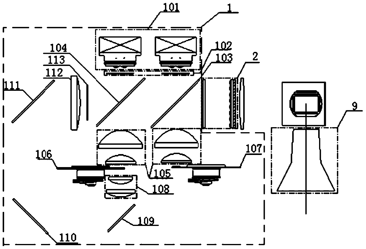
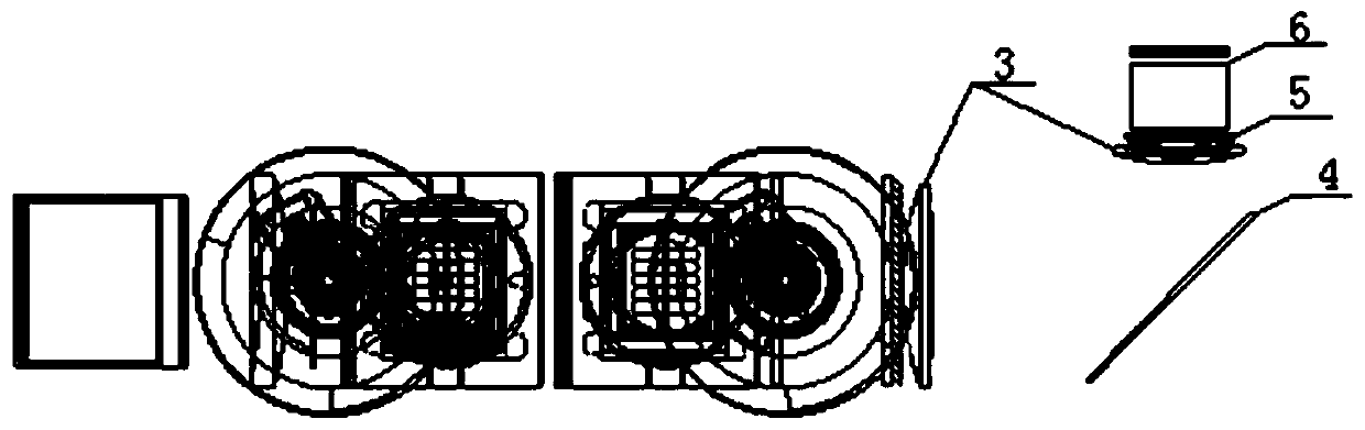
[0057] see figure 1 and figure 2 , figure 1 It is a front view of a laser TV projection system provided by an embodiment of the present invention, figure 2 A bottom view of a laser TV projection system provided for an embodiment of the present invention, including: a projection light source...


PUM

PropertyMeasurementUnit
Zhang jiaoaaaaaaaaaa

Abstract

The embodiment of the invention provides a laser television projection system. The laser television projection system comprises a projection light source module, a homogenizing and polarizing module,a phase plate, a PBS prism, a first LCOS light valve, a second LCOS light valve and a projection lens; the projection light source module provides a first white light light field; the homogenizing andpolarizing module is used for polarizing the first white light field to obtain a second white light field; the phase plate performs phase conversion on one of the time-sharing coupling light field and the third primary light in the second white light field to obtain a third white light field; p polarized light in the third white light field transmits through the PBS prism and then is reflected bythe first LCOS light valve to obtain a first reflection light field, and S polarized light in the third white light field is reflected at the PBS prism and then is reflected by the second LCOS lightvalve to obtain a second reflection light field which is transmitted to the projection mirror after passing through the PBS prism and the condition that too many lens elements are caused by the lightsplitting folding factor of a relay light path in a three-piece type light valve structure is avoided.

Description

technical field [0001] The invention relates to the technical field of laser display, in particular to a laser TV projection system. Background technique [0002] The laser TV projection system is a device that controls the projection light source through the light valve to obtain the projection image, and uses the projection lens to enlarge the projection image and display it on the projection screen. It is widely used in our lives. At present, laser TV projection systems mostly use single-chip light valves or three-chip light valves. Single-chip light valves use one light valve to load RGB (Red Green Blue, Red Green Blue) The chip light valve refers to the use of three light valves to load RGB signals respectively. [0003] At present, in the application of single-chip light valves, monochromatic pure laser light sources are generally used to excite RGB or RGBY (Red Green Blue Yellow) fluorescent wheels. Due to the influence of time division, the display brightness is not...

Claims


Application Information

Patent Timeline
IPC IPC(8): H04N9/31G03B21/20
CPCH04N9/3161G03B21/204G03B21/2073H04N9/3158H04N9/3164H04N9/3167H04N9/3111G03B21/006G03B33/12G02B27/1026G02B27/283G02B27/286G02B3/04G02B5/0205G02B5/0278G02B5/26G02B5/3083G02B26/008G02B27/0922G02B27/0927G02B27/0938G02B27/30G02B27/48G02F1/0136G02F1/136277G02F2203/02G03B21/005G03B21/2013G03B21/2066G03B21/208
Inventor 张金旺曹腾林威志王先炉刘志刚
Owner BEIJING ASU TECH CO LTD
Features
  • R&D
  • Intellectual Property
  • Life Sciences
  • Materials
  • Tech Scout
  • Unparalleled Data Quality
  • Higher Quality Content
  • 60% Fewer Hallucinations
Learn More