Floating clamping jaw, retarder stator and rotor clamp and using method thereof

A floating jaw, stator and rotor technology, applied in the field of jaw fixtures, can solve the problems of large turning runout and unstable clamping, and achieve the effect of ensuring machining accuracy and fixing stability.

Inactive Publication Date: 2019-10-11
SHAANXI FAST AUTO DRIVE GROUP CO LTD
View PDF10 Cites 0 Cited by
  • Summary
  • Abstract
  • Description
  • Claims
  • Application Information

AI Technical Summary

Problems solved by technology

[0003] The main purpose of the present invention is to solve the problem that the existing claws cannot avoid the ribs of the stator and rotor blank, resulting in unstable clamping and large turning jump, and to provide a floating claw, retarder stator and rotor fixture and its use method

Method used


Image

  • Floating clamping jaw, retarder stator and rotor clamp and using method thereof
  • Floating clamping jaw, retarder stator and rotor clamp and using method thereof
  • Floating clamping jaw, retarder stator and rotor clamp and using method thereof

Examples


Embodiment Construction

[0036] The technical solutions in the embodiments of the present invention will be clearly and completely described below in conjunction with the accompanying drawings in the embodiments of the present invention. Obviously, the described embodiments are not limiting to the present invention.

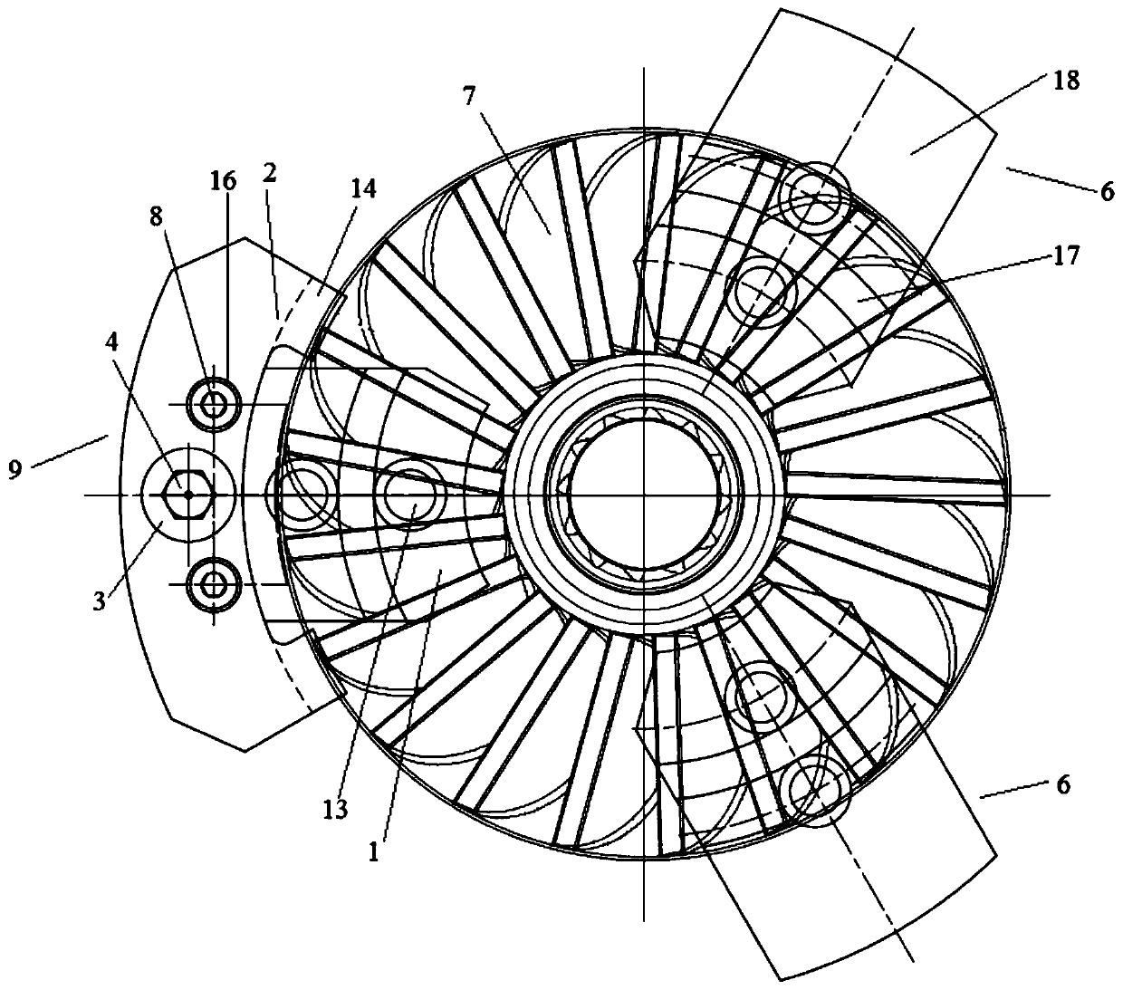
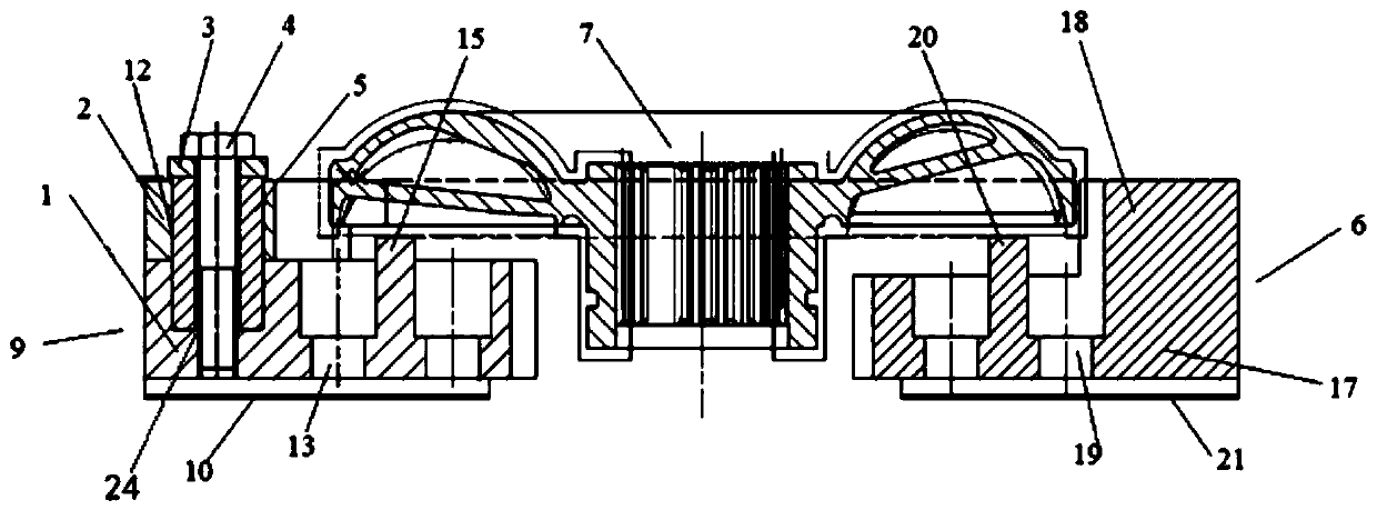
[0037] Reference figure 1 with figure 2 , A floating jaw of the present invention, the first jaw base 1 and the first jaw body 2 are both fan-shaped, and the first jaw body 2 is placed above the first jaw base 1, and its width is smaller than that of the first jaw. The arc length of the claw base 1 is greater than that of the first claw base 1, and the two side surfaces of the first claw body 2 extend beyond the two side surfaces of the first claw base 1, and the excess value is the same. The first jaw base 1 is provided with a stepped hole 24, and the small hole of the stepped hole 24 is provided with a thread; the large hole of the stepped hole 24 is arranged coaxially with the mandrel th...


PUM


Abstract

The invention belongs to clamping jaw clamps, and particularly relates to a floating clamping jaw, a retarder stator and rotor clamp and a using method thereof. The problem of large turning jumping caused by unstable clamping due to the fact that an existing clamping jaw cannot avoid a stator and rotor blank rib is solved. A floating clamping jaw and two fixing clamping jaws are adopted, due to the arrangement of contact foot bosses, the contact between the inner surface of the floating clamping jaw and the surface of a stator and rotor work piece is reduced, a rib on the surface of the work piece can be well avoided, the processing instability caused by contact of a clamp and the rib is avoided, in addition, a stator and a rotor are clamped on the clamp, firstly, the two fixing clamping jaws are in contact with the outer wall of the work piece, then, one contact foot boss of the floating clamping jaw can be in contact with the outer wall of the work piece,due to the fact that the clamping jaws and a base can relatively rotate along a core shaft, slight floating can be generated in the clamping process until the other contact foot boss of the floating claw is also in contact with the outer wall of the work piece, so that clamping is realized under the condition that four ribs cast by the stator and the rotor are avoided.

Description

Technical field [0001] The invention belongs to a jaw clamp, and particularly relates to a floating jaw, a retarder stator and rotor clamp and a use method thereof. Background technique [0002] In some retarder assemblies, the stator and rotor may still fail to meet the standards after being processed. Analyzing the current situation and processing flow, it is found that the wall thickness of the stator and rotor is uneven after turning. The reason is that the stator and rotor blank casting will leave four ribs on its outer circle. The ordinary three-jaw positioning is used during turning, and the clamping positions are evenly distributed. On the outer wall of the stator and rotor, the four ribs cannot be completely avoided, which will cause unstable clamping and large jumps after turning, which will affect the positioning of subsequent processes and ultimately affect the dynamic balance of the product. Summary of the invention [0003] The main purpose of the present invention ...

Claims


Application Information

Patent Timeline
Patent Type & Authority Applications(China)
IPC IPC(8): B23B31/103
CPCB23B31/103
Inventor 姚煊
Owner SHAANXI FAST AUTO DRIVE GROUP CO LTD
Why Eureka
Try Eureka