A metal pipe cutting device

A technology of cutting device and metal pipe fittings, applied in the direction of pipe shearing device, shearing device, accessories of shearing machine, etc. The effect of burrs and burrs, improving cutting quality, and improving heat dissipation speed

Active Publication Date: 2020-07-28
HEBEI UNIV OF TECH
View PDF13 Cites 0 Cited by
  • Summary
  • Abstract
  • Description
  • Claims
  • Application Information

AI Technical Summary

Problems solved by technology

Although the price is low and the operation is simple, when cutting metal pipe fittings, due to the low rigidity of the metal pipe fittings and the poor heat dissipation of the grinding wheel during the cutting process, it is easy to cause shrinkage and burrs on the incision of the metal pipe fittings, and the shrinkage length produced by cutting can reach the diameter of the pipe. One-fifth of the pipe diameter, the necking can reach one-tenth of the pipe diameter
[0003] The document with application number 201410324463.3 discloses a cutting system for thin-walled pipe fittings. The cutting system clamps the pipe fittings through the movement of the positioning rod driven by the cylinder piston rod. There are multiple axial cooling holes on the cutter head; Only the pipe to be cut can be clamped, and the cut piece cannot be clamped, which will cause the cutting point to shift and produce burrs; and the cutting pipe will not move so that the same cutting point receives a large one-way cutting feed force and residual heat, so that A large shrinkage is produced; while the axial cooling holes on the cutter head are good for heat dissipation, but they do not directly dissipate heat to the blade, and the heat dissipation effect is poor

Method used


Image

  • A metal pipe cutting device
  • A metal pipe cutting device
  • A metal pipe cutting device

Examples


Embodiment Construction

[0031] Specific examples of the present invention are given below. The specific embodiments are only used to further describe the present invention in detail, and do not limit the protection scope of the claims of the present application.

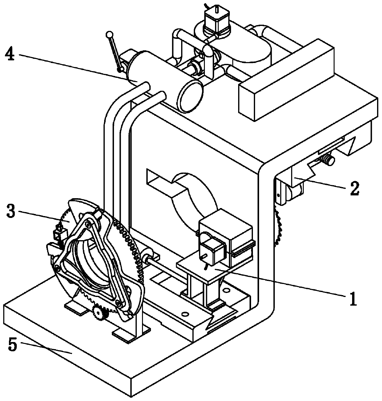
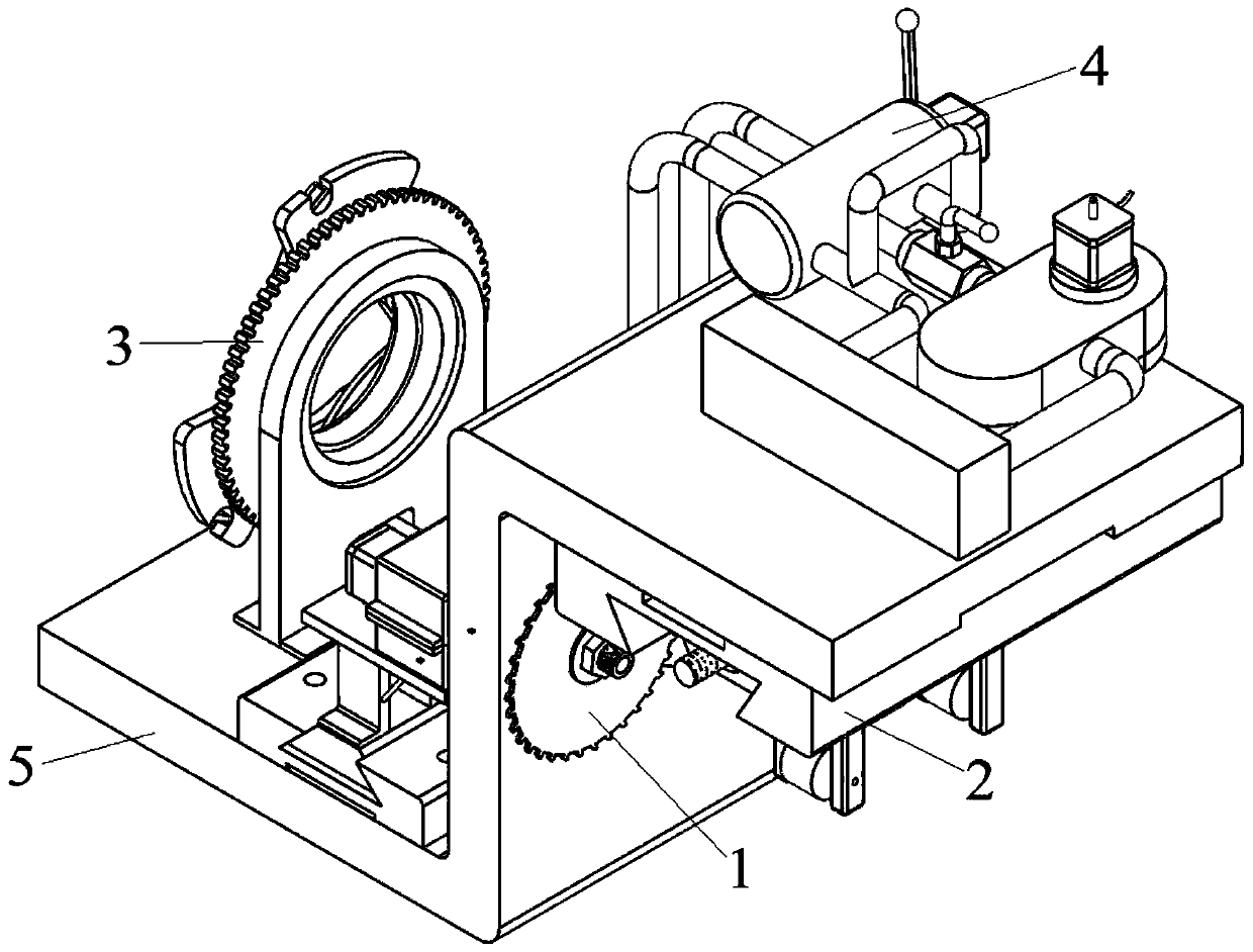
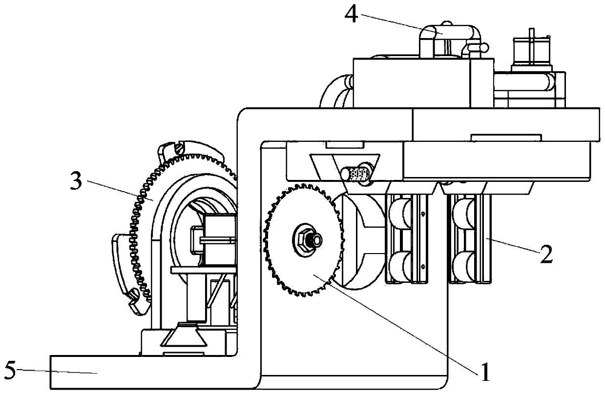
[0032] The invention provides a metal pipe cutting device (referred to as cutting device, see Figure 1-10 ), characterized in that the cutting device includes a cutting mechanism 1, a first clamping mechanism 2, a second clamping mechanism 3, a feed mechanism 4 and a frame 5; the first clamping mechanism 2 and the second clamping mechanism 3 are both It is a self-centering clamping mechanism; the frame 5 is Z-shaped, including an upper wing plate 51, a lower wing plate 52 and a side plate 53; the upper wing plate 51 and the lower wing plate 52 are fixed on two sides of the side plate 53 Side; have positioning hole 531 on the side plate 53, be used for the passage of metal pipe; Have the notch 532 that communicates with locating hole 531 o...


PUM


Abstract

The invention discloses a metal pipe fitting cutting device which comprises a cutting mechanism, a first clamping mechanism, a second clamping mechanism, a feeding mechanism and a rack. The first clamping mechanism comprises a bidirectional screw rod, a support seat, a second base and a clamping part; the second clamping mechanism comprises a rotary supporting bearing, a triangular fixed frame, aclamping tooth block, a connecting pillar, a supporting seat, a pinion, a locking stud, a locking block, a second motor, a sliding plate, a positioning stud and a bolt. In the cutting process, a metalpipe fitting rotates through the second clamping mechanism, and cutting points on the metal pipe fitting are ceaselessly changed during circumferential movement, so that the occurrence of the phenomena of throats and burrs caused by notch heat deformation and a unidirectional cutting feeding force is retarded. Through a combined clamping manner of the first clamping mechanism and the second clamping mechanism, only the degree of freedom of the metal pipe fitting rotating around a center shaft is kept, so that the metal pipe fitting cannot produce radial runout, and the cutting accuracy is improved.

Description

technical field [0001] The invention relates to the field of cutting and processing equipment, in particular to a cutting device for metal pipe fittings, in particular to a cutting device for thin-walled non-deformable metal pipe fittings. Background technique [0002] Grinding wheel cutting machine is a widely used processing equipment. Although the price is low and the operation is simple, when cutting metal pipe fittings, due to the low rigidity of the metal pipe fittings and the poor heat dissipation of the grinding wheel during the cutting process, it is easy to cause shrinkage and burrs on the incision of the metal pipe fittings, and the shrinkage length produced by cutting can reach the diameter of the pipe. One-fifth of the pipe diameter, the necking can reach one-tenth of the pipe diameter. [0003] The document with application number 201410324463.3 discloses a cutting system for thin-walled pipe fittings. The cutting system clamps the pipe fittings through the mo...

Claims


Application Information

Patent Timeline
Patent Type & Authority Patents(China)
IPC IPC(8): B23D21/00B23D33/00B23D33/02
CPCB23D21/00B23D33/00B23D33/02
Inventor 檀润华王康李浩宇何川孙建广陈梦雨
Owner HEBEI UNIV OF TECH
Why Eureka
Try Eureka