Longitudinal loop energy-saving type oil control valve

An oil control valve, energy-saving technology, applied in the direction of valve devices, mechanical equipment, engine components, etc., can solve the problems of high fuel consumption, high fluid medium pressure dependence, complex engine system structure, etc., to improve the phase adjustment speed , the effect of reducing consumption

Pending Publication Date: 2019-10-11
MIANYANG FULIN PRECISION MACHINING
View PDF0 Cites 8 Cited by
  • Summary
  • Abstract
  • Description
  • Claims
  • Application Information

AI Technical Summary

Problems solved by technology

[0003] At present, the common variable valve timing adjustment system mainly uses the oil pump to output the oil pressure to the oil control valve as the driving force. The oil control valve has a complicated structure and is highly dependent on the fluid medium pressure (oil pressure). The large amount of oil requires higher oil pressure and pump oil volume requirements for the engine oil pump system, resulting in a more complex structure of the engine system. Moreover, it must rely on a high drive oil pressure ratio to compensate for oil leakage; especially in low temperature conditions Under low conditions, the response speed of the variable valve timing adjustment system is low due to the high viscosity of the oil

Method used


Image

  • Longitudinal loop energy-saving type oil control valve
  • Longitudinal loop energy-saving type oil control valve
  • Longitudinal loop energy-saving type oil control valve

Examples


Embodiment Construction

[0020] In order to make the object, technical solution and advantages of the present invention clearer, the present invention will be described in detail below in conjunction with the accompanying drawings and specific embodiments. It should be understood that the specific embodiments described here are only used to explain the present invention, not to limit the present invention.

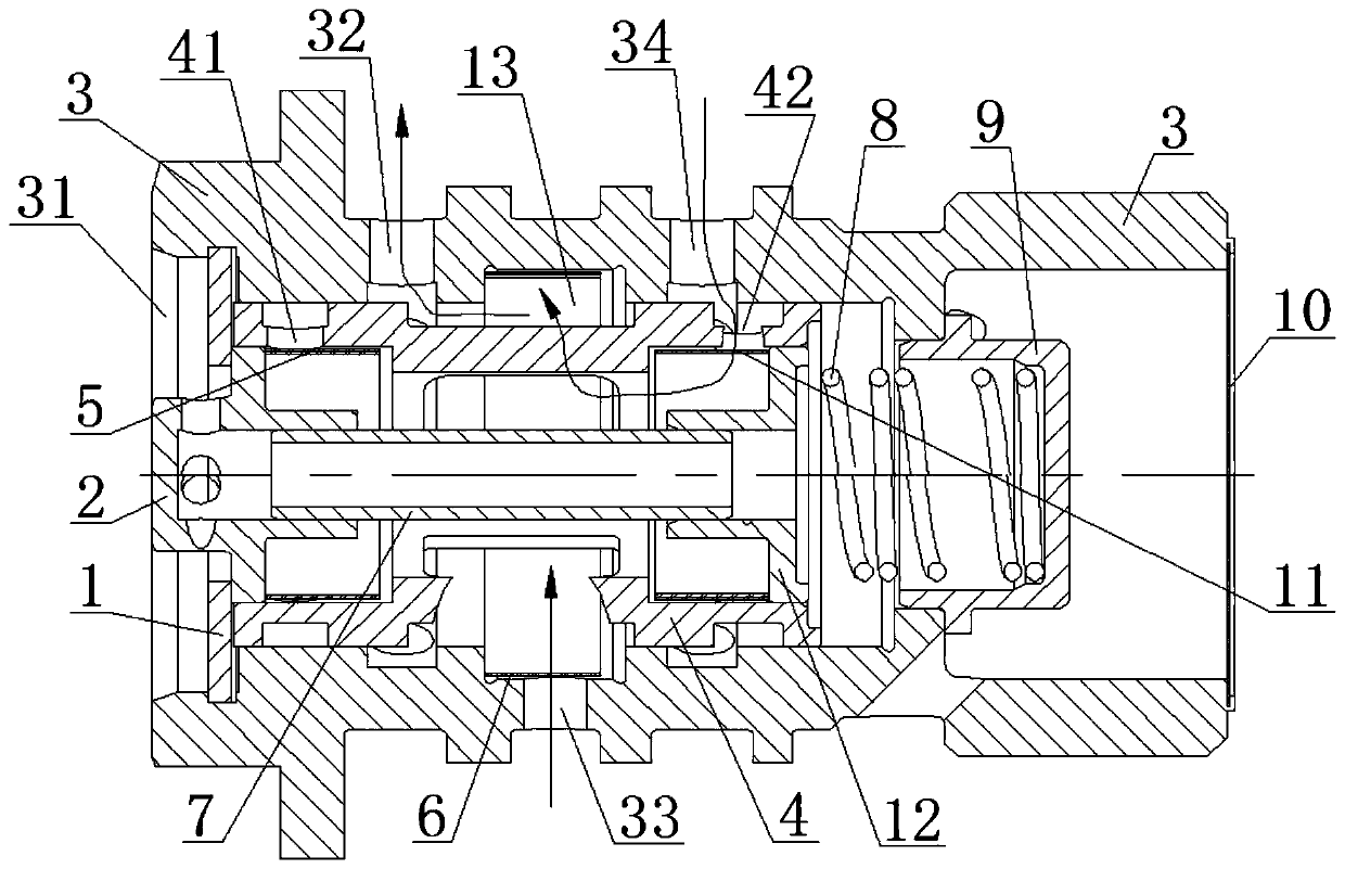
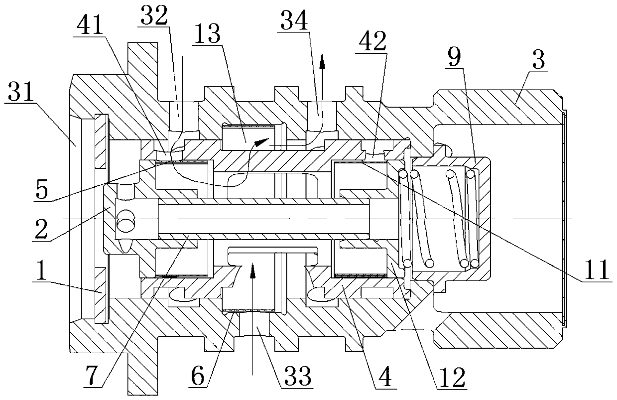
[0021] Such as figure 1 , figure 2 The shown radial circuit energy-saving oil control valve mainly includes a valve housing 3 and a piston 4. The valve housing 3 and the piston 4 are both hollow cavity structures, and the valve housing 3 is respectively formed with an air getter 31, a first The working interface 32 , the oil inlet 33 and the second working interface 34 , the second radial check valve 6 is installed in the hollow cavity of the valve housing 3 , and the filter screen 10 is fixedly connected to the inlet of the end of the valve housing 3 . A first oil port 41 and a second oil port...


PUM


Abstract

The invention provides a longitudinal loop energy-saving type oil control valve. The valve comprises a valve housing and a piston, the valve housing is provided with a first working interface and a second working interface, a longitudinal flow passage is formed between the piston and the valve housing, a second oil connecting hole and a second oil connecting hole are formed in the piston, a firstlongitudinal one-way valve and a third longitudinal one-way valve are installed in a hollow cavity of the piston, the first working interface, the first oil connecting hole, the first longitudinal one-way valve and the longitudinal flow passage are sequentially communicated in the process where the piston slides relative to the valve housing, or the second working interface, the second oil connecting hole, the third longitudinal one-way valve and the longitudinal flow passage are sequentially communicated. According to the oil control valve, the flow route of a fluid medium is changed by the first longitudinal one-way valve and the third longitudinal one-way valve, flow direction controlling is conducted, and therefore the consumption on the fluid medium can be effectively reduced; when the oil control valve is applied to a variable valve timing adjusting system, and the phase-position adjusting speed can be improved.

Description

technical field [0001] The invention relates to the field of structural design of an oil control valve, in particular to a radial loop energy-saving oil control valve. Background technique [0002] Variable valve timing adjustment technology refers to changing the overlapping angle of the intake and exhaust valves by controlling the opening angle of the intake and exhaust valves of the internal combustion engine under specific engine conditions, thereby increasing the intake charge and Efficiency, to better organize the intake vortex, adjust the cylinder explosion pressure and residual exhaust gas volume, and finally obtain comprehensive performance improvements such as engine power, torque, emissions, and fuel economy. [0003] At present, the common variable valve timing adjustment system mainly uses the oil pump to output the oil pressure to the oil control valve as the driving force. The oil control valve has a complicated structure and is highly dependent on the fluid m...

Claims


Application Information

Patent Timeline
Patent Type & Authority Applications(China)
IPC IPC(8): F01L1/344
CPCF01L1/3442F01L2001/34426
Inventor 赵敬刚谢超华张林张金伟赵军唐俊齐邱豪
Owner MIANYANG FULIN PRECISION MACHINING
Why Eureka
Try Eureka