
Linear constant current driving module circuit

A drive module, linear constant current technology, applied in the direction of adjusting electrical variables, control/regulation systems, instruments, etc., can solve the problems of low resistance conversion efficiency, and achieve low conversion efficiency, low power consumption, and reduced resistance Effect

Pending Publication Date: 2019-10-11
贵州辰矽电子科技有限公司
View PDF0 Cites 0 Cited by
  • Summary
  • Abstract
  • Description
  • Claims
  • Application Information

AI Technical Summary

Problems solved by technology

[0004] The technical problem to be solved by the present invention is to provide a linear constant current drive module circuit to solve the technical problem of low conversion efficiency of the linear constant current drive module circuit in the prior art due to the low conversion efficiency of the sampling resistor under high current conditions

Method used


Image

  • Linear constant current driving module circuit
  • Linear constant current driving module circuit
  • Linear constant current driving module circuit

Examples


Embodiment

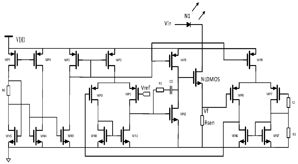
[0014] Example: such as figure 1 As shown, a linear constant current drive module circuit includes an error amplifier, a sampling voltage circuit and a low-voltage multiple amplifier circuit. The output terminal of the error amplifier is connected to the sampling voltage circuit, and the sampling voltage circuit is connected to the input terminal of the low-voltage multiple amplifier circuit. The output of the circuit is connected to the inverting terminal of the error amplifier, the input terminal of the low-voltage multiplier amplifier is connected to the sampling resistor of the sampling voltage circuit, and the feedback voltage output Vf is connected to the error amplifier.

[0015] Preferably, the above-mentioned error amplifier includes a resistor R0, a resistor R1, a capacitor C0, an enhanced NMOS transistor MN0, an enhanced NMOS transistor MN1, an enhanced NMOS transistor MN2, an enhanced NMOS transistor MN3, an enhanced NMOS transistor MN4, an enhanced NMOS transistor...


PUM


Abstract

The invention discloses a linear constant current driving module circuit, comprising an error amplifier, a sampling voltage circuit and a low voltage multiple amplifier circuit, wherein an output endof the error amplifier is connected with the sampling voltage circuit, the sampling voltage circuit is connected with an input end of the low voltage multiple amplifier circuit, the output end of thelow voltage multiple amplifier circuit is connected with an inverting end of the error amplifier, and the input end of the low voltage multiple amplifier circuit is connected with a sampling resistorof the sampling voltage circuit to access a feedback voltage output Vf to the error amplifier. The linear constant current driving module circuit disclosed by the invention reduces the sampling resistance, achieves a method of improving the efficiency, reduces the resistance of the sampling resistor, reducing the consumed power, improves the overall conversion power, and solves the technical problem of low conversion efficiency of the linear constant current driving module circuit in the prior at due to the sampling resistance in the case of large current.

Description

technical field [0001] The invention relates to a linear constant current drive module circuit, which belongs to the technical field of integrated power supplies. Background technique [0002] With the advancement of science and the development of e-commerce, people have higher and higher requirements for power management chips for consumer and portable applications. Portable electronic products play a vital role in daily life. Whether it is a tablet, mobile phone, handheld computer or other portable electronic products powered by batteries, there will be different functional modules. Different functions in the same electronic product Modules may require different values ​​of current or voltage. Without a stable current or voltage, electronic products cannot work properly. Taking constant current load as an example, LED is a semiconductor light-emitting diode. From its volt-ampere characteristic curve, we can know that a small change in voltage will cause a large change in ...

Claims


Application Information

Patent Timeline
Patent Type & Authority Applications(China)
IPC IPC(8): G05F3/26
CPCG05F3/26
Inventor 杨盘柱杨小兵王壮
Owner 贵州辰矽电子科技有限公司
Learn More